
A prefabricated prestressed concrete composite beam with cast-in-place conical connectors and its construction method

A technology of conical connectors and concrete, which is applied in the direction of load-bearing elongated structural components, building components, buildings, etc., can solve the problems of component instability, difficulty in ensuring prestressing, and difficult prestressing of concrete, etc., to achieve The effect of increased strength, fast construction speed and high prefabrication rate

Active Publication Date: 2022-06-24
XI'AN UNIVERSITY OF ARCHITECTURE AND TECHNOLOGY
View PDF0 Cites 0 Cited by
  • Summary
  • Abstract
  • Description
  • Claims
  • Application Information

AI Technical Summary

Problems solved by technology

[0002] In the research process of prestressed steel-concrete composite beams, it is difficult to ensure that all the prestress is accurately applied to the concrete of the lower flange, and part of the prestress is inevitably borne by the steel and the concrete of the upper flange.
Simply separating the concrete and the section steel, and applying prestress to the lower concrete flange on one side will not only cause the concrete of the compression flange to bear part of the prestress, but also cause the prestressed concrete to be under compression due to large bias before assembly. Cracks appear on one side or even the whole component becomes unstable and damaged
Therefore, a simple and effective prestressed steel-concrete composite beam with a simple principle is needed to solve the problem that the prestress is difficult to be completely and accurately applied to the concrete on the tension side

Method used


Image

  • A prefabricated prestressed concrete composite beam with cast-in-place conical connectors and its construction method
  • A prefabricated prestressed concrete composite beam with cast-in-place conical connectors and its construction method
  • A prefabricated prestressed concrete composite beam with cast-in-place conical connectors and its construction method

Examples


Embodiment Construction

[0036] The embodiments of the present invention will be described in detail below with reference to the accompanying drawings and examples.

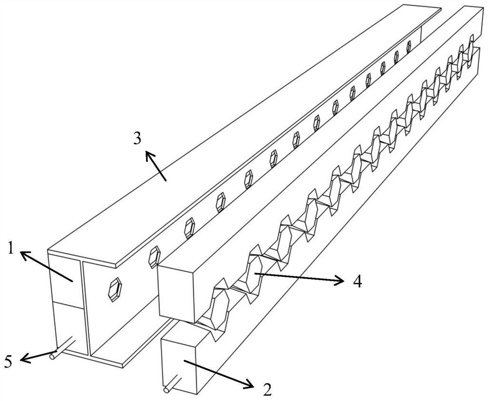
[0037] like figure 1 As shown, a prefabricated prestressed concrete composite beam with cast-in-place conical connecting pieces, comprising:

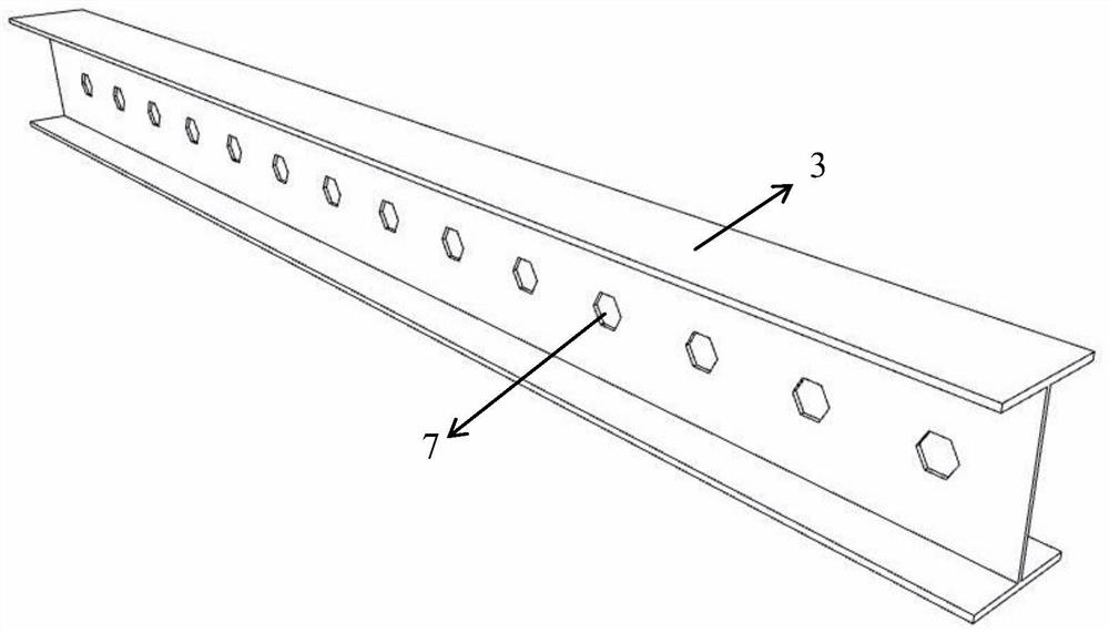
[0038] Honeycomb type I-beam 3, reference figure 2 , there are holes 7 on its web. For example, the holes 7 are regular hexagons, and the plurality of holes 7 are evenly arranged along the length direction of the honeycomb-shaped I-beam 3 . In the up-down direction, there is generally only one row of holes 7, but multiple rows can also be provided according to actual conditions such as size and strength requirements. When multiple rows are provided, the holes 7 in each row may be located in the same vertical direction, or may be staggered in the up-down direction.

[0039] The split concrete strips are arranged on both sides of the web of the honeycomb I-beam 3, and between the upper and lowe...


PUM


Abstract

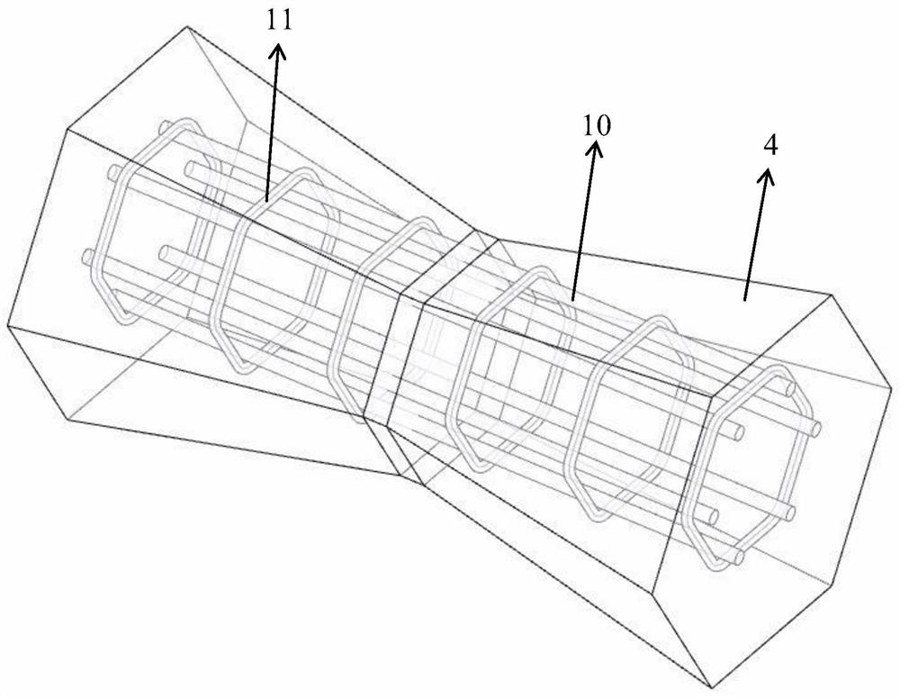
A steel prefabricated prestressed concrete composite beam with cast-in-place conical connectors, comprising: a honeycomb-shaped I-steel with holes on its web; split concrete strips arranged on both sides of the web of the honeycomb-shaped I-steel , and is located between the upper and lower flanges, on which there are via holes corresponding to the holes, and the diameter of the via holes increases along the direction of the web to both sides; the cast-in-place concrete connectors are poured in the via holes and holes, and the The honeycomb type I-beam is connected with the split concrete strip as a whole, which is thin in the middle and thick at both ends, so as to fix the position of the split concrete strip and play the role of longitudinal shear resistance; the prestressed tendon is set in the split concrete inside the bar, and is consistent with the length direction of the honeycomb I-beam; while ensuring that the prestress is accurately applied to the concrete, the concrete part can limit the out-of-plane displacement of the steel web and flange in the compression zone, increasing its surface external stability.

Description

technical field [0001] The invention belongs to the technical field of construction, in particular to a prefabricated prestressed concrete composite beam with cast-in-place conical connecting pieces and a construction method. Background technique [0002] In the research process of prestressed steel-concrete composite beam, it is difficult to ensure that all the prestress is applied to the concrete of the lower flange accurately, and part of the applied prestress cannot be avoided by the steel and the concrete of the upper flange. Simply separating the concrete and the section steel and applying prestress to the lower flange of the concrete on one side will not only cause the concrete of the compression flange to bear part of the prestress, but also cause the prestressed concrete to be under compression due to large bias before it is assembled. Cracks occur on one side or even the entire component is unstable and damaged. Therefore, a simple and effective prestressed steel-...

Claims


Application Information

Patent Timeline
Patent Type & Authority Patents(China)
IPC IPC(8): E04C3/293
CPCE04C3/293
Inventor 杨勇贺九州于云龙薛亦聪冯世强黄慧萍李彬彬刘永涛弓欢学
Owner XI'AN UNIVERSITY OF ARCHITECTURE AND TECHNOLOGY
Learn More