A power cable stripping device

A technology for power cables and cable bodies, applied in the field of power cable stripping devices, can solve the problems of difficult to control cutting force, low cable stripping efficiency, easy damage to conductive cores, etc., and achieves the effects of increasing stripping quality, reducing damage and increasing flexibility

Active Publication Date: 2022-02-15
JIANGSU SANQI CABLE & WIRE
View PDF5 Cites 1 Cited by
  • Summary
  • Abstract
  • Description
  • Claims
  • Application Information

AI Technical Summary

Problems solved by technology

[0006] In order to make up for the deficiencies of the prior art, when the cable is docked or repaired outdoors in the prior art, the skin insulation layer of the cable body is cut by a cutter, but since the insulation layer is usually tightly wrapped in a conductive On the outer periphery of the core, it is difficult to peel off the insulation layer completely and without adhesion by a cutter, resulting in low cable stripping efficiency. At the same time, the hardness of the cable insulation layer is high under low temperature conditions. It is time-consuming and laborious to peel off by a cutter, and the cutting force is difficult to control. The problem of easily damaging the conductive core, a power cable stripping device proposed by the present invention

Method used


Image

  • A power cable stripping device
  • A power cable stripping device
  • A power cable stripping device

Examples


Embodiment 1

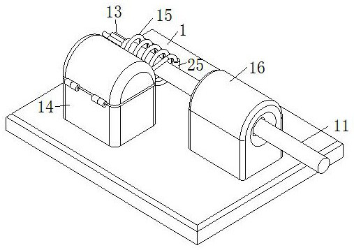
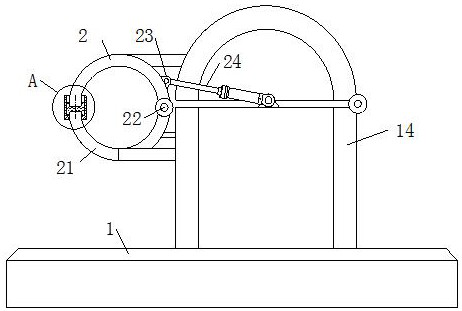
[0033] Such as Figure 1 to Figure 7 As shown, a power cable stripping device according to the present invention includes a workbench 1, a cutting unit and a heating unit; a cable body 11 runs through the middle of the cutting unit, and the cable body 11 includes an insulating layer 12 and a conductive core 13; The heating unit includes a heating table 14 and a high-frequency heating coil 15, the high-frequency heating coil 15 is connected to a power supply through a high-frequency generator, and the high-frequency heating coil 15 is coaxially arranged with the cable body 11; the cutting unit includes a cutting table 16, The driving roller 17 and the driven roller 18, the driving roller 17 and the driven roller 18 are symmetrically arranged, and the cable body 11 runs through the gap between the driving roller 17 and the driven roller 18; the driven roller 18 is rotationally connected with the cutting table 16 , the driving roller 17 is driven by a reduction motor; the middle ...

Embodiment 2

[0041] Such as Figure 8 to Figure 9 Shown, comparative example one, wherein another kind of implementation mode of the present invention is:

[0042] Described lifting unit comprises supporting column 4, and supporting column 4 is arranged on the both sides of rotating shaft 39, and supporting column 4 is provided with chute 41, and rotating shaft 39 is embedded in chute 41 and is slidably connected with chute 41, and the two ends of rotating shaft 39 are rotatably connected with Axle sleeve 42, the bottom of the axle sleeve 42 is provided with a push rod 43, and the bottom end of the push rod 43 is covered with a cylinder 44; the corresponding position of the cylinder 44 is rotatably connected with a worm gear 45, and one side of the worm gear 45 is meshed with a The worm 46 is driven to rotate by the lifting motor 47; one side of the worm wheel 45 is fixedly connected with a cam 48 at the position corresponding to the ejector rod 43; The rod 43 and the driving roller 17 ri...


PUM


Abstract

The invention belongs to the technical field of electric power equipment, and specifically relates to a power cable stripping device, which includes a workbench, a cutting unit and a heating unit; a cable body runs through the middle of the cutting unit, and the cable body includes an insulating layer and a conductive core; The heating unit includes a heating table and a high-frequency heating coil, the high-frequency heating coil is connected to a power supply through a high-frequency generator, and the high-frequency heating coil is arranged coaxially with the cable body; the cutting unit includes a cutting table, a driving roller and a driven roller, The driving roller and the driven roller are symmetrically arranged, and the cable body runs through the gap between the driving roller and the driven roller; the driven roller is connected to the cutting table in rotation, and the driving roller is driven by a reduction motor; the middle part of the driving roller is fixedly connected with Disc-shaped cutter; After passing the cable body through the driving roller and the driven roller, the high-frequency heating coil heats the cable body, and then the cutter cuts the insulation layer quickly and stably, reducing the impact of uneven cutting force on the conductor core damage.

Description

technical field [0001] The invention belongs to the technical field of power equipment, in particular to a power cable stripping device. Background technique [0002] In power lines, the proportion of cables is gradually increasing. Power cable is a cable product used to transmit and distribute high-power electric energy in the main line of the power system; however, the traditional power cable stripping device has poor effect and low efficiency due to cumbersome and complicated design. [0003] There are also some technical solutions about cable stripping devices in the prior art. For example, a Chinese patent with application number 2018104015343 discloses a power cable stripping device, including that the device places the cable body in a downward pressure sequence from right to left. After the clamping block and the three cable rollers are mounted, start the first servo drive motor to drive the circular gear to rotate. According to the meshing principle of the rack and ...

Claims


Application Information

Patent Timeline
Patent Type & Authority Patents(China)
IPC IPC(8): H02G1/12
CPCH02G1/126H02G1/127H02G1/1275
Inventor 王新飞
Owner JIANGSU SANQI CABLE & WIRE
Why Eureka
Try Eureka