
Internal and external tooth centering control structure and machining method of high-speed precise heavy-load herringbone gear ring

A processing method and a technology of internal and external teeth, which are applied to gear tooth manufacturing devices, manufacturing tools, components with teeth, etc., can solve problems such as moderate control deviation and instability

Active Publication Date: 2021-11-30
HANGZHOU ADVANCE GEARBOX GRP
View PDF12 Cites 0 Cited by
  • Summary
  • Abstract
  • Description
  • Claims
  • Application Information

AI Technical Summary

Problems solved by technology

[0007] In order to solve the problem that the accumulative errors in the machining process of a large heavy-duty ring gear with internal and external herringbone teeth lead to unstable control deviations between the center plane of the inner tooth and the center plane of the outer tooth, the purpose of the present invention is to provide a high-speed precision The centering control structure and processing method of the internal and external teeth of the heavy-duty herringbone gear ring adopts the method of processing the internal teeth separately first, and then processing the external teeth together. Facilitate alignment and alignment, improve efficiency, reduce error accumulation, and improve machining accuracy

Method used


Image

  • Internal and external tooth centering control structure and machining method of high-speed precise heavy-load herringbone gear ring
  • Internal and external tooth centering control structure and machining method of high-speed precise heavy-load herringbone gear ring
  • Internal and external tooth centering control structure and machining method of high-speed precise heavy-load herringbone gear ring

Examples


Embodiment 1

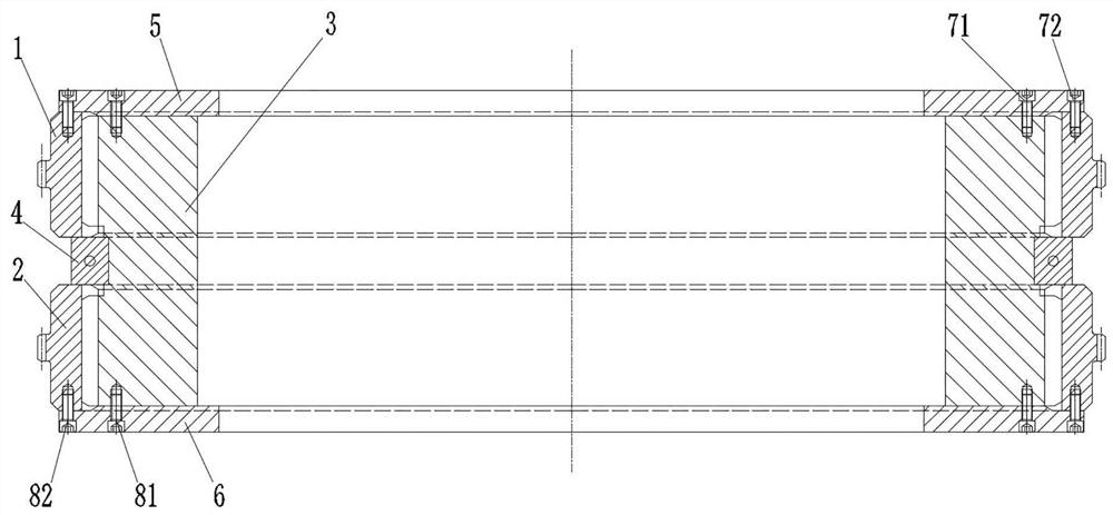
[0044] A centering control processing method of internal and external teeth of a high-speed precision heavy-duty herringbone ring gear, including a first ring gear 1, a second ring gear 2 and a correction tool; the correction tool includes a correction part 3, a positioning part 4, a first pressing Part 5 and the second pressing part 6, such as image 3 and Figure 4 As shown, a first helical tooth 32 and a second helical tooth 33 are provided on the outer peripheral surface of the correcting member 3, the first helical tooth 32 and the second helical tooth 33 cooperate to form a herringbone tooth structure, and the positioning member 4 is sleeved on the correcting member 3 and between the first helical tooth 32 and the second helical tooth 33; the specific steps are as follows:

[0045] Step 1), complete the grooving, heat treatment and grinding of the internal helical teeth of the first ring gear 1 and the second ring gear 2 respectively; where one end face of the first rin...


PUM


Abstract

The invention discloses an internal and external tooth centering control structure and a machining method of a high-speed precise heavy-load herringbone gear ring. Internal oblique teeth of two gear rings are separately machined, the size precision of the internal teeth is improved through fine grinding machining, so that the internal teeth of the left-handed gear ring and the right-handed gear ring are symmetrical with high precision, and the central planes are centered; then the left-handed gear ring and the right-handed gear ring are spliced and calibrated on a calibration tool, the two gear rings are sleeved on the same calibration piece, so that the two gear rings are coaxial; the external teeth of the calibration piece are meshed with the internal teeth of the two gear rings respectively, so that the phase angles of the two gear rings are consistent; the two gear rings are clamped and fixed on the calibration piece through two pressing pieces respectively, so that the two gear rings are completely attached to the two end faces of a positioning piece, and the central plane of the positioning piece is the central plane of the internal herringbone teeth and is also used as the machining reference of the central plane of the external herringbone teeth for external tooth machining; and the machining requirements of the centering precision and the high precision are met, the machining efficiency is improved, and the mass production machining is facilitated.

Description

technical field [0001] The invention relates to the field of gear processing, in particular to a centering control structure and processing method of internal and external teeth of a high-speed precision heavy-duty herringbone ring gear. Background technique [0002] The herringbone tooth is a kind of cylindrical gear. The herringbone tooth is composed of two sets of helical teeth with different rotation directions on the left and right. Gear meshing transmission, high bearing capacity, stable transmission, especially suitable for applications in heavy machinery, such as ships and other high-power transmission occasions. [0003] The plane where the left and right tooth extension lines of the herringbone teeth intersect is the center plane of the herringbone tooth. When there is a phase difference or a coaxiality error between the two sets of helical teeth of the herringbone tooth, the center plane will be different from the theoretically designed center plane. Displacement...

Claims


Application Information

Patent Timeline
IPC IPC(8): B23F7/00B23F23/00B23F23/06
CPCB23F7/00B23F23/00B23F23/06
Inventor 柳志丰金海明赵菲姚红燕祝红炬任印喜
Owner HANGZHOU ADVANCE GEARBOX GRP
Learn More