Eureka AIR delivers breakthrough ideas for toughest innovation challenges, trusted by R&D personnel around the world.

Plate cutting device and method

A technology of cutting device and cutting method, which is applied in the direction of metal processing equipment, welding equipment, manufacturing tools, etc., can solve the problems of low cutting efficiency, poor economy, and arching of product parts, so as to improve cutting efficiency, reduce processing cost, The effect of avoiding damage

Pending Publication Date: 2021-11-30
FOREWIN FPC SUZHOU
View PDF8 Cites 0 Cited by
  • Summary
  • Abstract
  • Description
  • Claims
  • Application Information

AI Technical Summary

Problems solved by technology

[0003] In order to overcome the defects in the prior art, those skilled in the art can easily think of using a mechanical cutter instead of a laser light source for cutting, but in the actual trial process, the inventor found that the product part obtained after cutting the plate with a mechanical cutter will produce arching, Therefore, only using a mechanical tool laser light source cannot meet the cutting requirements in actual production, that is, the above technical solution is not feasible
[0004] The embodiment of the present invention provides a plate cutting device and method, which are used to solve the above-mentioned problems of low cutting efficiency, poor economy and occurrence of arching

Method used


Image

  • Plate cutting device and method
  • Plate cutting device and method

Examples


Embodiment Construction

[0025] The following will clearly and completely describe the technical solutions in the embodiments of the present invention with reference to the accompanying drawings in the embodiments of the present invention. Obviously, the described embodiments are only some, not all, embodiments of the present invention. Based on the embodiments of the present invention, all other embodiments obtained by persons of ordinary skill in the art without making creative efforts belong to the protection scope of the present invention.

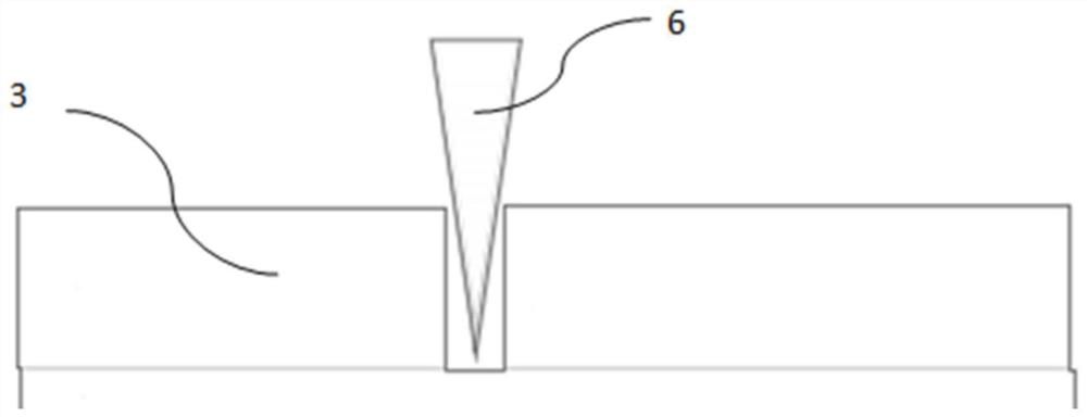
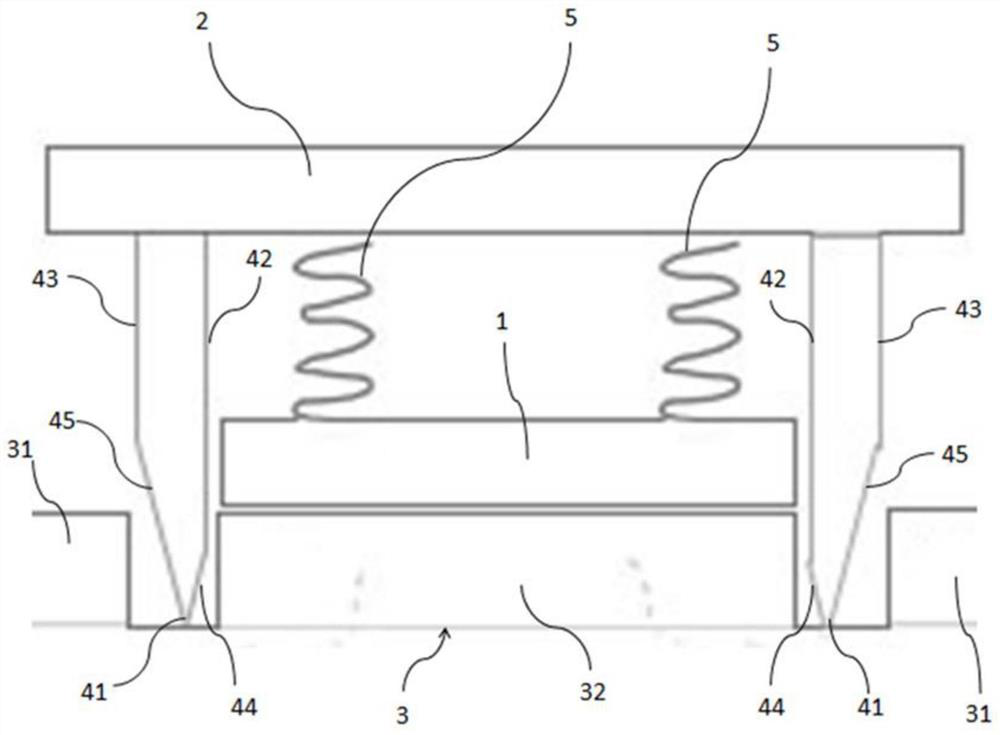
[0026] like figure 2 As shown, the plate cutting device of the present embodiment includes:

[0027] The first fixing part 1, the first fixing part 1 can be in contact with the plate 3, so that the entire cutting device can be positioned on the plate 3 through the abutment of the first fixing part 1 and the plate 3, thereby improving the stability of the entire cutting device during operation sex.

[0028] The second fixing part 2, the second fixing part 2 ...


PUM


Abstract

The invention discloses a plate cutting device and method. The device comprises a first fixing part which can abut against a plate; a second fixing part is elastically connected with the first fixing part in the first direction away from the plate, the second fixing part is fixedly provided with a cutting unit extending in the first direction, and the cutting unit comprises a cutter body and a cutter head arranged at the end, away from the second fixing part, of the cutter body; and the cutter body is provided with a first side edge close to the first fixing part and a second side edge far away from the first fixing part, the projection of the cutter head in the first direction is close to the first side edge, and a first distance value exists between the projection of the cutter head and the first side edge. A required product part can be obtained through one-time cutting, the influence of high temperature on the plate is also avoided, and therefore the cutting efficiency is improved. In addition, the machining cost and the maintenance cost of equipment are reduced, arches on the product part are eliminated, and the product part meeting the requirements is obtained.

Description

technical field [0001] The invention relates to the field of material cutting, in particular to a plate cutting device and method. Background technique [0002] The plate cutting device is a device used to cut the plate, and it is mainly used to process hard plates or soft and hard plates in the actual processing process. The existing plate cutting device first uses an image recognition system to identify the area to be cut of the plate, and then uses a laser light source to cut the plate, thereby cutting the plate into the required product part and the remaining waste part. However, the existing plate cutting device adopts laser cutting as a cutting method, so it needs to cut the plate multiple times during the cutting process, and after cutting, because the laser light source has high temperature characteristics, it will damage the plate so that carbon will be generated on the cutting edge. Powder remains, so that the cutting efficiency is not high. In addition, due to th...

Claims


Application Information

Patent Timeline
Patent Type & Authority Applications(China)
IPC IPC(8): B23K26/38B23K26/70
CPCB23K26/38B23K26/702
Inventor 皇甫铭陈林伟
Owner FOREWIN FPC SUZHOU
Why Eureka
Eureka Blog
Learn More