
Laser cutting machine for intelligent manufacturing

A laser cutting machine and intelligent manufacturing technology, applied in manufacturing tools, laser welding equipment, welding equipment, etc., can solve the problems of lack of fixing at the cutting port of the plate, affecting the cutting accuracy, and uneven force on the plate

Pending Publication Date: 2021-11-30
YULIN NORMAL UNIVERSITY
View PDF10 Cites 4 Cited by
  • Summary
  • Abstract
  • Description
  • Claims
  • Application Information

AI Technical Summary

Problems solved by technology

[0004] The purpose of the present invention is to provide a laser cutting machine for intelligent manufacturing to solve the problem of cutting the edge of the plate through the fixed structure during the existing cutting proposed in the above background technology, and then cut the position where the plate needs to be cut. However, there is a lack of fixing at the cutting port of the plate, resulting in the problem that when cutting, as the cutting point of the plate melts, the force on the plate is uneven, which in turn affects the cutting accuracy.

Method used


Image

  • Laser cutting machine for intelligent manufacturing
  • Laser cutting machine for intelligent manufacturing
  • Laser cutting machine for intelligent manufacturing

Examples


Embodiment Construction

[0023] The following will clearly and completely describe the technical solutions in the embodiments of the present invention with reference to the accompanying drawings in the embodiments of the present invention. Obviously, the described embodiments are only some, not all, embodiments of the present invention. Based on the embodiments of the present invention, all other embodiments obtained by persons of ordinary skill in the art without making creative efforts belong to the protection scope of the present invention.

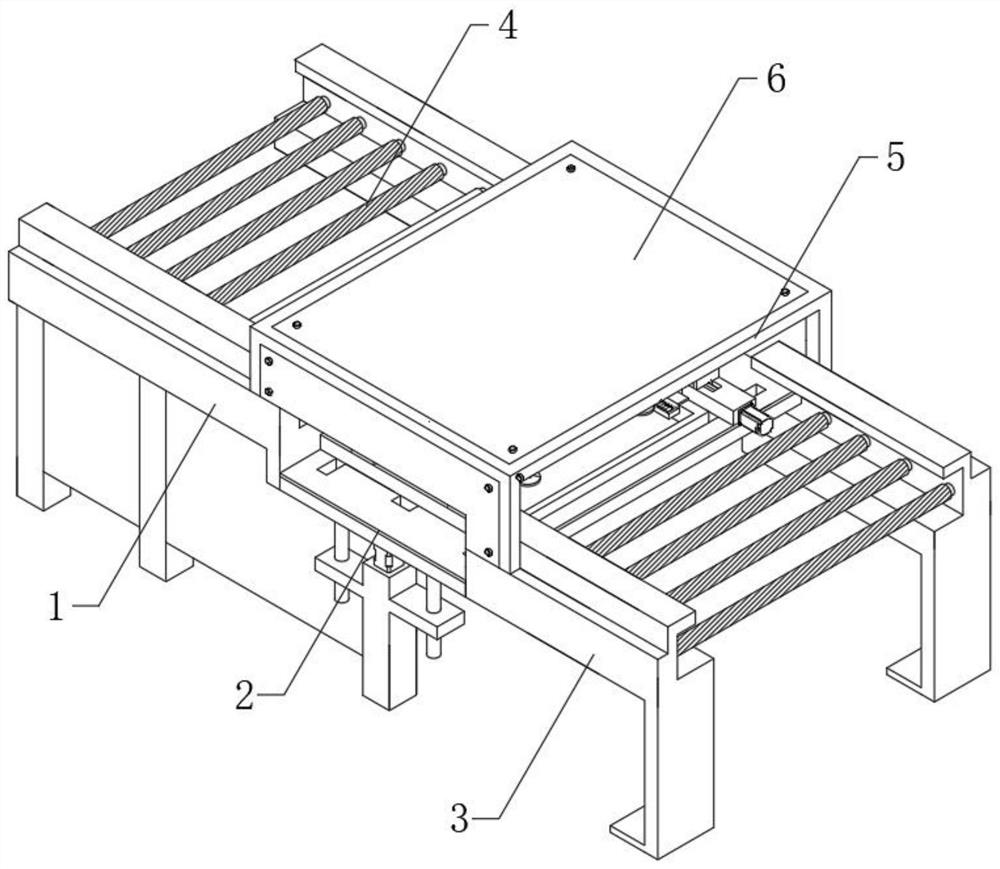
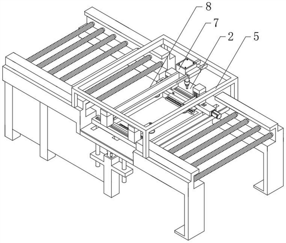
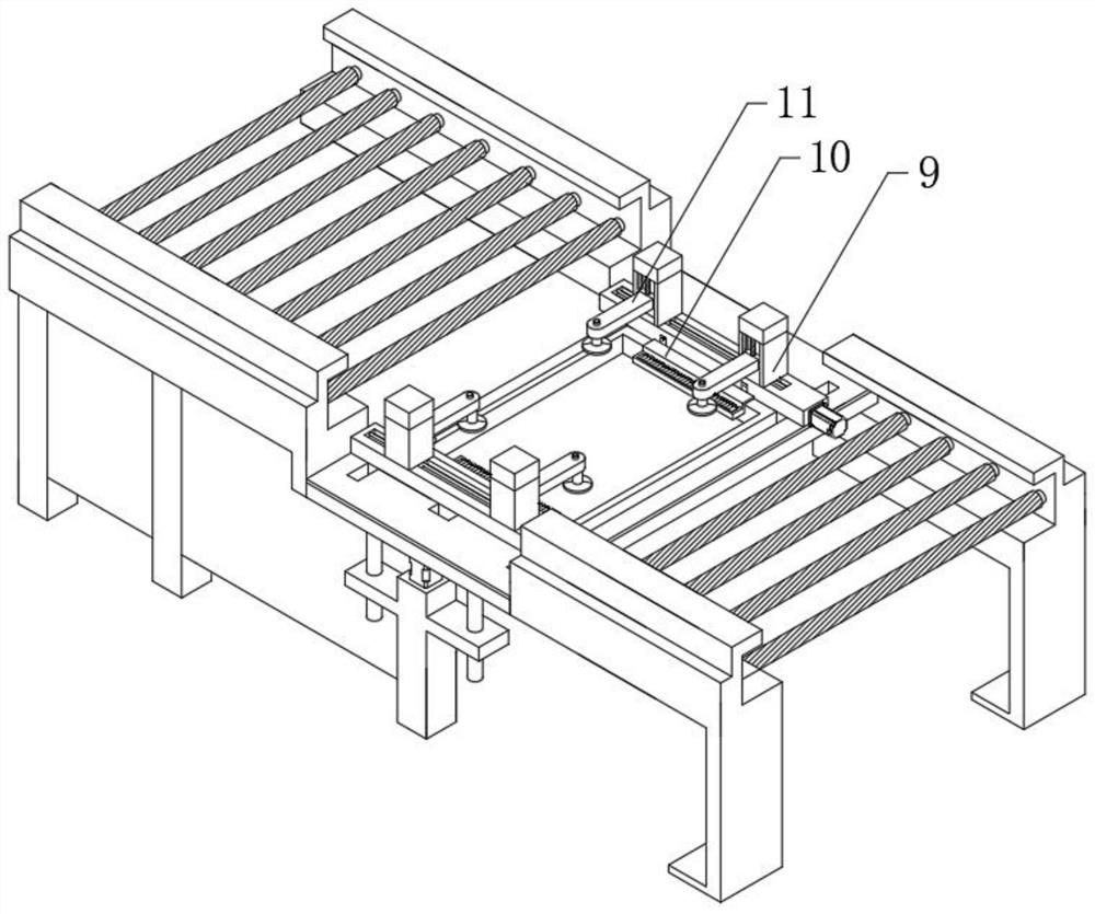
[0024] see Figure 1-5 , the present invention provides a technical solution of a laser cutting machine for intelligent manufacturing: a laser cutting machine for intelligent manufacturing, including a feeding platform 1, a processing platform 2, a discharging platform 3, a material guide roller 4, and a laser frame 5. Laser cutting seat 7, mobile cutting support 8, pressure bar seat 9, traction plate 10, first motor 12, second motor 16 and electric hydraulic ...


PUM


Abstract

The invention discloses a laser cutting machine for intelligent manufacturing. The laser cutting machine comprises a feeding rack, a machining rack, a discharging rack, a guide roller, a laser frame, a laser cutting base, a movable cutting support, pressing rod bases, a traction plate, a first motor, a second motor and an electric hydraulic cylinder. The two ends of two transverse plate grooves are in sliding connection with the two ends of two supporting transverse plates, a top groove is formed at the top end of each supporting transverse plate, and two pressing rod bases are in sliding connection into the top grooves through small sliding blocks. According to the laser cutting device, the machining rack is arranged between the feeding rack and the discharging rack, the distance between the two supporting transverse plates can be adjusted, and the cutting requirements of plates with different widths are met; and meanwhile, two pressing rod bases capable of being adjusted in a sliding manner are arranged on the supporting transverse plates, the first motor drives a first screw rod to rotate, so that a first sliding block slides in the pressing rod bases, then a pressing rod and a circular pressing piece are driven to press downwards, a cutting point is fixed and limited, and the situation that the cutting precision is affected due to the fact that the plate moves in the cutting process is prevented.

Description

technical field [0001] The invention relates to a laser cutting machine, in particular to a laser cutting machine for intelligent manufacturing, which belongs to the technical field of plate cutting. Background technique [0002] Laser cutting is the use of high-power-density laser beams to irradiate the material to be cut, so that the material is quickly heated to the vaporization temperature, and evaporates to form holes. As the beam moves to the material, the holes continuously form narrow slits to complete the cutting of the material. Cutting, because there is no tool processing cost, so laser cutting equipment is also suitable for the production of small batches of parts of various sizes that could not be processed before. Laser cutting equipment usually uses computerized digital control technology devices. After using this device, you can use telephone lines Accept cutting data from a CAD workstation. [0003] In plate processing, fixed-point cutting is carried out by...

Claims


Application Information

Patent Timeline
Patent Type & Authority Applications(China)
IPC IPC(8): B23K26/38B23K26/70
CPCB23K26/38B23K26/702
Inventor 杨基鑫李玉霞李佑长陈鸿毅王焜洁
Owner YULIN NORMAL UNIVERSITY
Learn More