Radial Floating Spindle Device with Gravity Compensation

A technology of gravity compensation and spindle device, which is applied in the direction of grinding/polishing safety devices, manufacturing tools, and grinding machine parts, etc., which can solve the problem of uneven force on the spindle components, affecting product quality and precision, and difficulty in spindle grinding Constant force and determination of the main shaft, etc., to ensure the processing accuracy and processing efficiency, eliminate the influence of its own gravity, and facilitate repeated positioning

Active Publication Date: 2022-08-05
杭州龙砺智能科技有限公司
View PDF9 Cites 0 Cited by
  • Summary
  • Abstract
  • Description
  • Claims
  • Application Information

AI Technical Summary

Problems solved by technology

[0002] In the process of industrial production, grinding is a very common process. At present, most of them rely on manual grinding, which is time-consuming and laborious. The working environment on site is poor (such as large dust), and safety accidents occur from time to time, making the working environment of the grinding staff quite harsh. , nowadays, it is gradually becoming a trend to use robots or other automation equipment for grinding. The radial floating spindle device is a commonly used component of automation equipment. In the prior art, the initial state of the spindle assembly is due to its own gravity. Downward tilt, radial floating spindle device does not have gravity compensation function, so it will cause uneven force around the spindle assembly, unable to determine the center of the spindle assembly, etc., it is difficult to guarantee the processing accuracy and efficiency of the product
[0003] In view of this, a pneumatic floating spindle is disclosed in the patent document with the application number of 201920006519.9. The pneumatic floating spindle disclosed in the comparison document does not have the function of gravity compensation, and it is difficult to achieve grinding around the spindle during grinding. Constant force and determination of the axis of the spindle affect product quality and precision

Method used


Image

  • Radial Floating Spindle Device with Gravity Compensation
  • Radial Floating Spindle Device with Gravity Compensation
  • Radial Floating Spindle Device with Gravity Compensation

Examples


Embodiment Construction

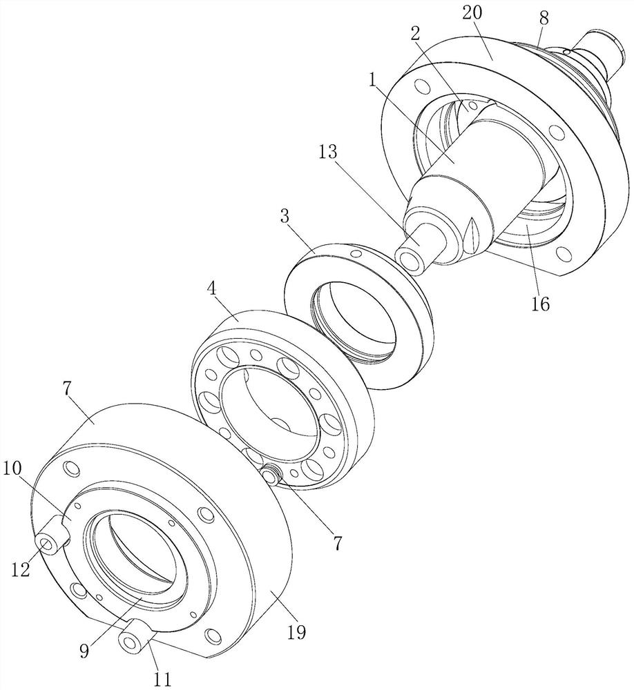
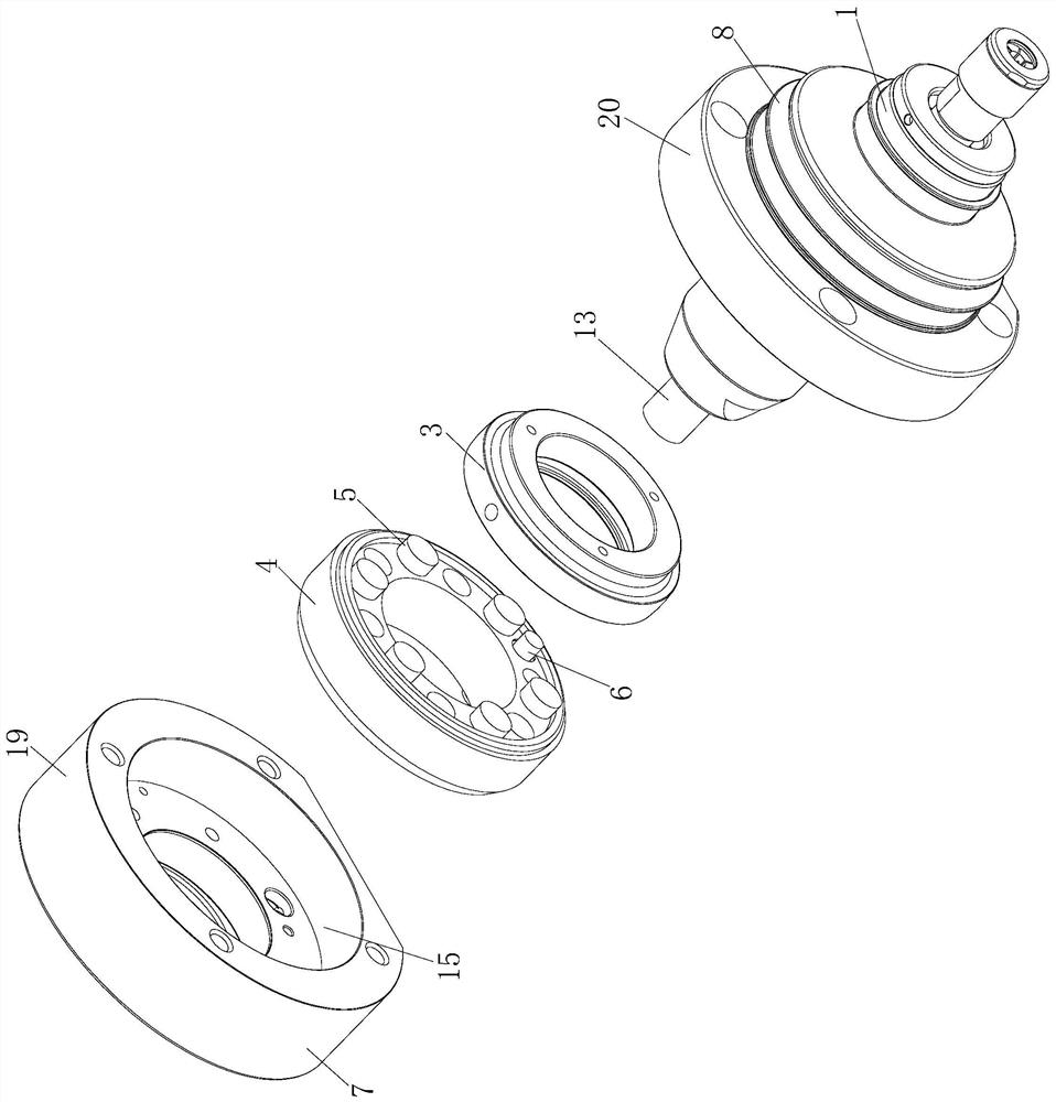
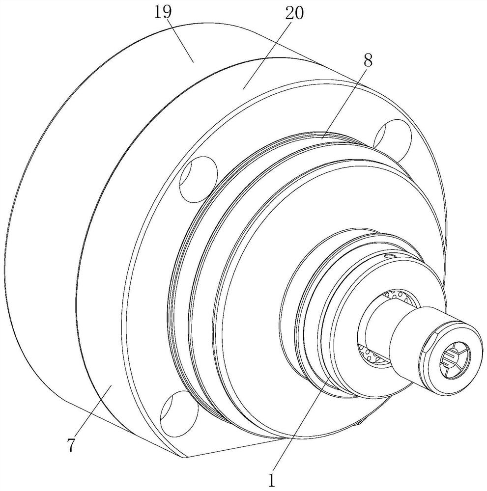
[0031] The present invention will be further described in detail below in conjunction with the accompanying drawings and through the examples. The following examples are to explain the present invention and the present invention is not limited to the following examples.

[0032] Example.

[0033] see Figure 1 to Figure 9 It should be noted that the structures, proportions, sizes, etc. shown in the drawings attached in this specification are only used to cooperate with the contents disclosed in the specification, so as to be understood and read by those who are familiar with the technology, and are not used to limit the present invention. The limited conditions that can be implemented have no technical significance. Any modification of the structure, change of the proportional relationship or adjustment of the size should still fall within the scope of the present invention without affecting the effect and the purpose that the present invention can achieve. It is within the s...


PUM


Abstract

The invention involves a radial floating spindle device with a gravity compensation function, which is the field of mechanical equipment.The invention includes the main axis component. Its structure is characterized by: also includes axis fixing ring, flexible shell, directional nut, piston column, air -guided mechanism, air -conducting base, air -guided air intake mouth, and directional intake mouth., Flexible housing and directional nuts are packed on the main axis component, and the axis fixed ring, flexible shell, and directional nuts are installed in the intake base.The gas guide agency is matched with the flexible shell, which is matched with a flexible shell and a shaft fixed ring.Both are matched with the directional nut.Avoid sloping the spindle component, which can facilitate determining the axis center of the main axis component, which is convenient for repeated positioning, and then ensure the processing accuracy and processing efficiency of the workpiece.

Description

technical field [0001] The invention relates to a radial floating main shaft device with gravity compensation function, belonging to the field of mechanical equipment. Background technique [0002] In the industrial production process, grinding is a very common process. At present, most of them rely on manual grinding, which is time-consuming and labor-intensive, and the on-site working environment is poor (such as large dust), and safety accidents occur from time to time, making the working environment of grinding staff quite harsh , Nowadays, the use of robots or other automation equipment for grinding has gradually become a trend. The radial floating spindle device is a commonly used component of automation equipment. In the prior art, because the spindle assembly is in the initial state due to its own gravity, the automation equipment will Downward tilt, the radial floating spindle device does not have the function of gravity compensation, so it will cause uneven force a...

Claims


Application Information

Patent Timeline
Patent Type & Authority Patents(China)
IPC IPC(8): B24B41/04B24B41/00B24B55/06B24B55/00
CPCB24B41/04B24B41/007B24B55/06B24B55/00
Inventor 林良德
Owner 杭州龙砺智能科技有限公司
Why Eureka
Try Eureka