Bridge concrete mixing equipment

A technology for mixing equipment and concrete, which is applied to clay preparation devices, cement mixing devices, cleaning methods and tools, etc. It can solve the problems of accelerated dust inhalation by construction workers, troublesome operation, and bulky volume, and achieve the goal of reducing dust inhalation and improving efficiency Effect

Pending Publication Date: 2021-11-30
安徽丰林建设工程有限公司
View PDF0 Cites 0 Cited by
  • Summary
  • Abstract
  • Description
  • Claims
  • Application Information

AI Technical Summary

Problems solved by technology

However, traditional concrete mixers are bulky and cumbersome to operate, making it difficult to transport them to bridges under construction.
If cement and gravel aggregates are directly used to build a mixing pit on site, and water is poured into the mixing pit for manual mixing, the open mixing space will easily cause dust to fly and accelerate the dust inhalation of construction workers.

Method used


Image

  • Bridge concrete mixing equipment
  • Bridge concrete mixing equipment
  • Bridge concrete mixing equipment

Examples


Embodiment 1

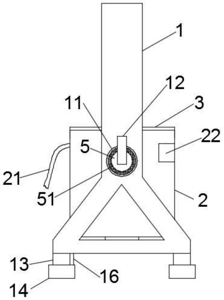
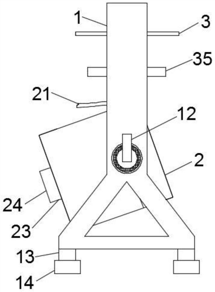
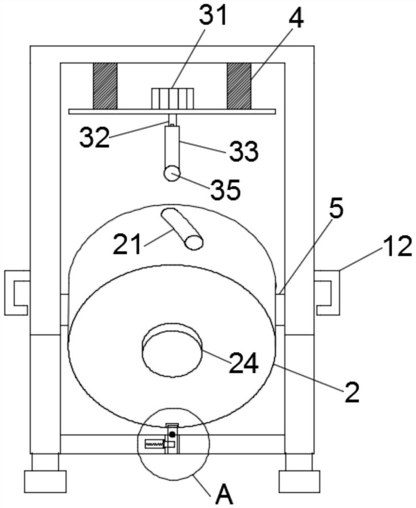
[0031] see Figure 1 to Figure 4 , the present invention provides a technical solution: a concrete mixing equipment for bridges, including a mixing tank and a support frame 1, the mixing tank includes a tank body 2 and a cover body 3, and the left and right ends of the tank body 2 are connected to the support frame through connecting columns 5 1 connection, the tank body 2 is provided with a water injection pipe 21, an observation window 22, a bottom outlet 23, an outlet cover 24 and a receiving hole 25, the outlet cover 24 is screwed to the bottom outlet 23, and the support frame 1 is connected to the receiving hole 25 through a positioning rod 16 , the cover body 3 is connected with the support frame 1 through two sets of symmetrical vertical electric telescopic rods 4, the cover body 3 is equipped with a stirring motor 31 and a stirring shaft, the output end of the stirring motor 31 is connected with the stirring shaft, and the stirring shaft is fixedly connected with a stir...

Embodiment 2

[0037] see Figure 1 to Figure 5 , the present invention provides a technical solution: a concrete mixing equipment for bridges, including a mixing tank and a support frame 1, the mixing tank includes a tank body 2 and a cover body 3, and the left and right ends of the tank body 2 are connected to the support frame through connecting columns 5 1 connection, the tank body 2 is provided with a water injection pipe 21, an observation window 22, a bottom outlet 23, an outlet cover 24 and a receiving hole 25, the outlet cover 24 is screwed to the bottom outlet 23, and the support frame 1 is connected to the receiving hole 25 through a positioning rod 16 , the cover body 3 is connected with the support frame 1 through two sets of symmetrical vertical electric telescopic rods 4, the cover body 3 is equipped with a stirring motor 31 and a stirring shaft, the output end of the stirring motor 31 is connected with the stirring shaft, and the stirring shaft is fixedly connected with a stir...

Embodiment 3

[0041] see Figure 1 to Figure 9 , the present invention provides a technical solution: a concrete mixing equipment for bridges, including a mixing tank and a support frame 1, the mixing tank includes a tank body 2 and a cover body 3, and the left and right ends of the tank body 2 are connected to the support frame through connecting columns 5 1 connection, the tank body 2 is provided with a water injection pipe 21, an observation window 22, a bottom outlet 23, an outlet cover 24 and a receiving hole 25, the outlet cover 24 is screwed to the bottom outlet 23, and the support frame 1 is connected to the receiving hole 25 through a positioning rod 16 , the cover body 3 is connected with the support frame 1 through two sets of symmetrical vertical electric telescopic rods 4, the cover body 3 is equipped with a stirring motor 31 and a stirring shaft, the output end of the stirring motor 31 is connected with the stirring shaft, and the stirring shaft is fixedly connected with a stir...


PUM


Abstract

The invention relates to the technical field of concrete mixing devices, in particular to bridge concrete mixing equipment which comprises a mixing tank and a supporting frame. The mixing tank comprises a tank body and a cover body, the left end and the right end of the tank body are connected with the supporting frame through connecting columns, and the tank body is provided with a water injection pipe, an observation window, a bottom outlet, an outlet cover and a bearing hole. The outlet cover is in threaded connection with the bottom outlet, the supporting frame is connected with the bearing hole through a positioning rod, the cover body is connected with the supporting frame through two sets of symmetrical vertical electric telescopic rods, the cover body is provided with a stirring motor and a stirring shaft, the output end of the stirring motor is connected with the stirring shaft, and the stirring shaft is fixedly connected with stirring blades. The stable and inclined tank body is convenient for shoveling cement and other solid raw materials before stirring and also convenient for digging the concrete in the tank body according to the use amount of the concrete in one time after stirring is completed, the phenomenon that an outlet of the tank body is blocked due to intermittent concrete taking is avoided, the closed tank body and the closed cover body prevent the raw materials from raising dust, and dust inhalation by on-site constructors is reduced.

Description

technical field [0001] The invention relates to the technical field of concrete mixing devices, in particular to concrete mixing equipment for bridges. Background technique [0002] Concrete mixing device is a device that mixes cement, sand and gravel aggregates and water and mixes them into concrete mixture. The traditional concrete mixer is mainly composed of a mixing drum, a feeding and unloading mechanism, a water supply system, a transmission mechanism, a frame and a supporting device. When working, the mixing drum rotates around its horizontal axis, and the materials added to the mixing drum are lifted by the blades. After reaching a certain height, it will fall by its own weight, and this repeated movement will achieve the effect of uniform mixing. However, traditional concrete mixers are bulky and cumbersome to operate, making it difficult to transport them to bridges under construction. If a mixing pit is directly built on site with cement and sand and gravel aggr...

Claims


Application Information

Patent Timeline
Patent Type & Authority Applications(China)
IPC IPC(8): B28C5/16B28C7/16B08B9/087
CPCB28C5/16B28C5/161B28C7/16B08B9/087
Inventor 胡朝鲜
Owner 安徽丰林建设工程有限公司
Why Eureka
Try Eureka