Eureka AIR delivers breakthrough ideas for toughest innovation challenges, trusted by R&D personnel around the world.

Magnetic material storage device and use method thereof

A technology for storage devices and magnetic materials, which is applied in the directions of packaging, transportation and packaging, and the type of packaged items, can solve the problems of the development direction of electric vehicles that do not conform to environmental protection, the reduction of use value, and the low amount of vehicle charging piles, so as to avoid Rust or corrosion, easy maintenance, no displacement effect

Pending Publication Date: 2021-11-30
深圳市贝贝特科技实业有限公司
View PDF0 Cites 0 Cited by
  • Summary
  • Abstract
  • Description
  • Claims
  • Application Information

AI Technical Summary

Problems solved by technology

[0002] With the continuous development of new energy, more and more new energy vehicles appear in our lives. Many families choose new energy vehicles as their first choice when purchasing a car. However, as the number of new energy vehicles continues to increase, vehicle charging However, the amount of supporting piles has been at a low level. For the roads in our country, there are no charging roads, and electric vehicle charging piles are only developed in cities. Environmentally friendly electric vehicles can only be driven in cities, so the application of electric vehicles has been subject to certain Restriction, use value reduction does not conform to the development direction of environmentally friendly electric vehicles

Method used


Image

  • Magnetic material storage device and use method thereof
  • Magnetic material storage device and use method thereof
  • Magnetic material storage device and use method thereof

Examples


Embodiment Construction

[0029] In order to express the present invention more clearly, the present invention will be further described below in conjunction with the accompanying drawings and embodiments.

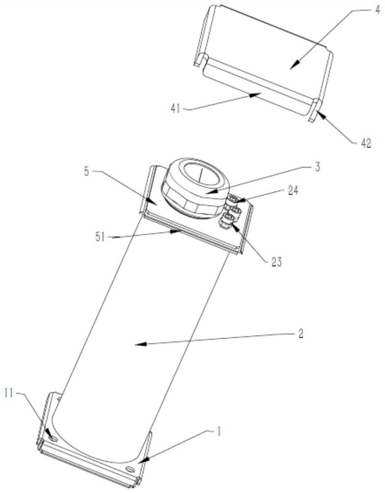
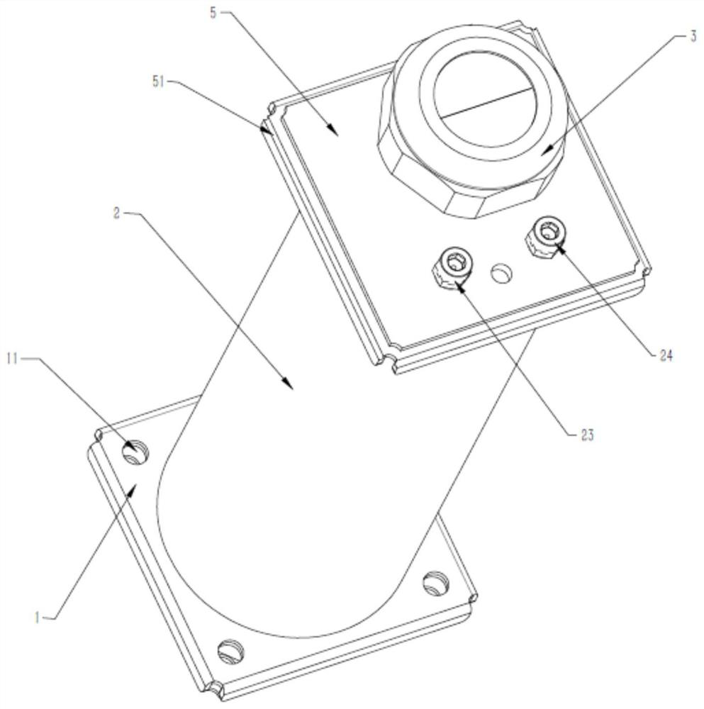
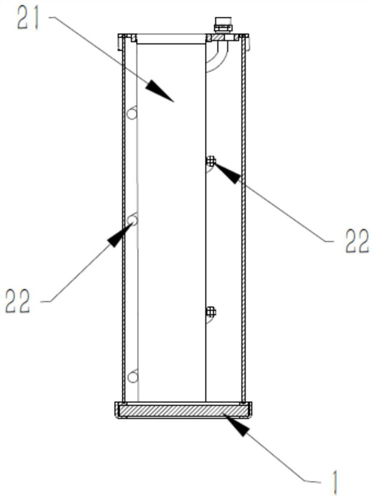
[0030] see Figure 1 to Figure 3 , the invention discloses a magnetic material storage device, comprising a base 1, a protective sleeve 2 and a protective head 3, one end of the protective sleeve 2 is fixedly connected with the base 1, and the other end is provided with a thread matching the protective head, The protective sleeve 2 is a hollow interlayer structure, including a first interlayer 21 and a second interlayer 22. The second interlayer 22 is surrounded by the outside of the first interlayer 21. The protective sleeve 2 is provided with a baffle on the side facing the protective head. The plate is fixedly connected with the protective sleeve 2, and through holes matching the first interlayer 21 and the second interlayer 22 are opened on the baffle. In this embodiment, the base is used to f...


PUM


Abstract

The invention discloses a magnetic material storage device and a use method thereof. The magnetic material storage device comprises a base, a protective sleeve and a protective head, one end of the protective sleeve is fixedly connected with the base, the other end of the protective sleeve is provided with threads matching the protective head, the protective sleeve is of a hollow interlayer structure and comprises a first interlayer and a second interlayer, the second interlayer annularly sleeves the first interlayer, a baffle is arranged on the side, facing the protective head, of the protective sleeve and fixedly connected with the protective sleeve, and through holes matching the first interlayer and the second interlayer are formed in the baffle. A permanent magnet is protected through a special structure, so that after the permanent magnet is buried underground, the permanent magnet can be effectively protected, the permanent magnet is prevented from rusting or being in an environment with large temperature difference, and the maximum charging effect is achieved through a special burying mode.

Description

technical field [0001] The invention relates to the field of road paving, in particular to a magnetic material storage device and a method for using the same. Background technique [0002] With the continuous development of new energy, more and more new energy vehicles appear in our lives. Many families choose new energy vehicles as their first choice when purchasing a car. However, as the number of new energy vehicles continues to increase, vehicle charging However, the amount of supporting piles has been at a low level. For the roads in our country, there are no charging roads, and electric vehicle charging piles are only developed in cities. Environmentally friendly electric vehicles can only be driven in cities, so the application of electric vehicles has been subject to certain The restriction and the reduction of use value are not in line with the development direction of environmentally friendly electric vehicles. [0003] Magnet charging for electric vehicles on the...

Claims


Application Information

Patent Timeline
Patent Type & Authority Applications(China)
IPC IPC(8): B60L53/12B60L53/30B65D81/18B65D81/36
CPCB60L53/12B60L53/30B65D81/18B65D81/36Y02T10/70Y02T10/7072Y02T90/12Y02T90/14
Inventor 程东升张田
Owner 深圳市贝贝特科技实业有限公司
Why Eureka
Eureka Blog
Learn More