Efficient and energy-saving furnace frame spraying and sintering equipment and using method thereof

A high-efficiency energy-saving, sintering equipment technology, applied in the field of furnace frame production and processing, can solve the problems of increasing the production cost of the furnace frame, wasting manpower and material resources, and costing a lot, and achieve the effects of saving gas, improving the quality of finished products, and improving processing efficiency

Pending Publication Date: 2021-11-30
济南圣铨智能制造有限公司
View PDF0 Cites 0 Cited by
  • Summary
  • Abstract
  • Description
  • Claims
  • Application Information

AI Technical Summary

Problems solved by technology

[0004] In the prior art, in the step of spraying glaze and then sintering and molding the grate, it is usually processed by distributing multiple times. It is necessary to load and unload the grate many times, which wastes a lot of manpower and material resources, and the grate The spraying process adopts the chain link conveyor line for conveying and spraying. Such spraying process needs to turn over the furnace frame, and spray a large amount of glaze on the chain link conveyor line, so as to avoid the accumulation of glaze on the chain link conveyor line. It takes a lot of water to clean the glaze on the chain link conveyor line, which is very waste water and greatly increases the production cost of the hob. Therefore, we propose a high-efficiency and energy-saving hob spraying and sintering equipment and its use method

Method used


Image

  • Efficient and energy-saving furnace frame spraying and sintering equipment and using method thereof
  • Efficient and energy-saving furnace frame spraying and sintering equipment and using method thereof
  • Efficient and energy-saving furnace frame spraying and sintering equipment and using method thereof

Examples


Embodiment

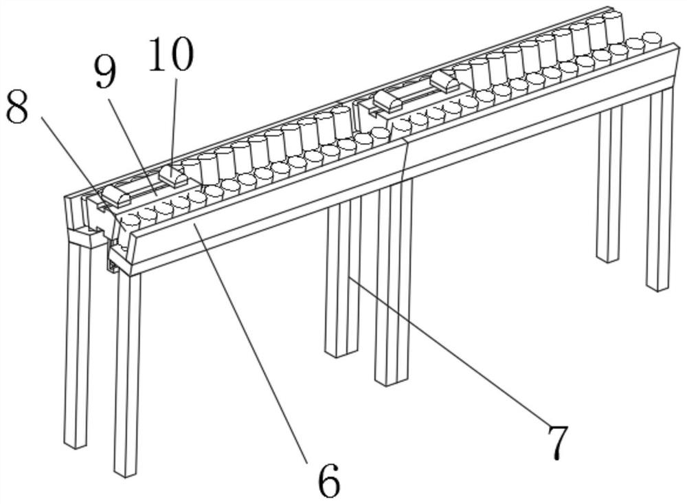
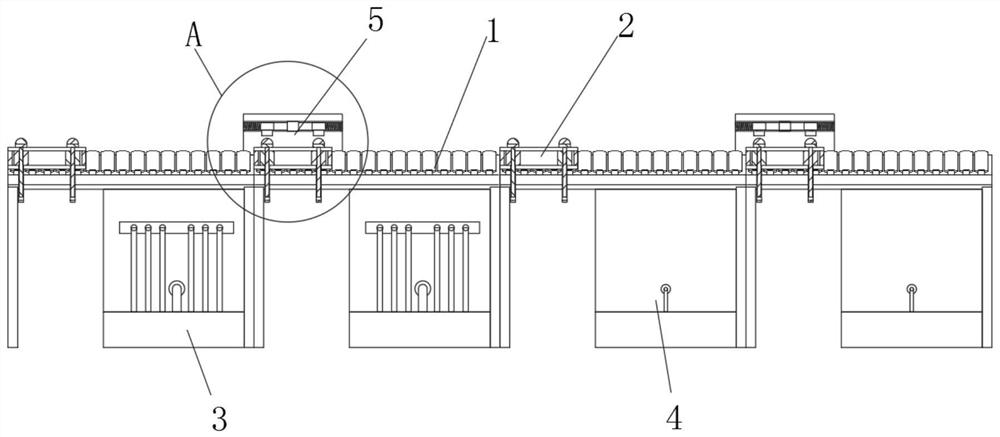
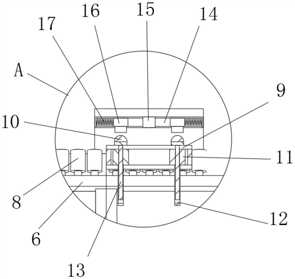
[0039] see Figure 1-5, a high-efficiency and energy-saving grate spraying and sintering equipment, including a conveying mechanism 1, a hoisting mechanism 2 is slidably connected to the conveying mechanism 1, two spraying mechanisms 3 and two sintering mechanisms 4 are arranged in sequence at the lower end of the conveying mechanism 1, and the hoisting mechanism Two pairs of supporting rods 12 and pressing rods 13 are arranged at the center of the lower end of 2. The lower ends of supporting rods 12 and pressing rods 13 clamp and fix the upper edge of the grate to be processed. There is a square gap, and the square gap is set corresponding to the position of the supporting rod 12 and the pressing rod 13. The sides of the square gap on the side of the spraying mechanism 3 are provided with rubber ribs 30, and the sides of the square gap on the side of the sintering mechanism 4 are provided with rock wool. Rib 31 .

[0040] Concretely, the conveying mechanism 1 includes two co...


PUM


Abstract

The invention discloses efficient and energy-saving furnace frame spraying and sintering equipment and a using method thereof, and belongs to the technical field of furnace frame producing and machining.The efficient and energy-saving furnace frame spraying and sintering equipment comprises a conveying mechanism, a hoisting mechanism is slidably connected to the conveying mechanism, and two spraying mechanisms and two sintering mechanisms are sequentially arranged at the lower end of the conveying mechanism; and two pairs of supporting rods and pressing rods are arranged in the center of the lower end of the hoisting mechanism, through cooperation of the conveying mechanism and the hoisting mechanism, the furnace frame to be machined is conveyed to sequentially pass through inner cavities of the spraying mechanisms and the sintering mechanisms, spraying and sintering machining are conducted on the furnace frame to be machined through the spraying mechanisms and the sintering mechanisms, the two faces of the furnace frame are machined at the same time, the continuous processing greatly improves the processing efficiency of the furnace frame, and the suspended hoisting of the hoisting mechanism effectively avoids the overflow of glaze and flame, so that the gas is saved while the conveying mechanism does not need to be cleaned, and the efficient and energy-saving furnace frame spraying and sintering equipment is more energy-saving and environment-friendly.

Description

technical field [0001] The invention relates to the technical field of furnace frame production and processing, in particular to a high-efficiency and energy-saving furnace frame spraying and sintering equipment and a use method thereof. Background technique [0002] The enamel hob is one of the daily necessities. The biggest requirement for it is high temperature resistance. If it cannot withstand high temperature, there may be porcelain explosion or deformation, which seriously affects the use of the enamel hob. [0003] In the manufacturing process of the original enamelled furnace frame, the grate blank was first manufactured by the mold casting process, but the molten iron penetration in the mold casting process is not uniform and there are defects such as sand holes, less meat and more meat, etc. After the blank is manufactured, it will be coated with glaze , and then sintered by the cupola firing process. [0004] In the prior art, in the step of spraying glaze and t...

Claims


Application Information

Patent Timeline
Patent Type & Authority Applications(China)
IPC IPC(8): C23D11/00C23D5/02C23D7/00C23D9/00
CPCC23D11/00C23D5/02C23D7/00C23D9/00
Inventor 董淑勇曹鑫于化军孙会平刘中平李金海
Owner 济南圣铨智能制造有限公司
Why Eureka
Try Eureka