Automatic cleaning device of condensing equipment

A technology for automatic cleaning and condensing equipment, applied in the direction of cleaning heat transfer devices, lighting and heating equipment, drying solid materials, etc., can solve the problems of labor-intensive, low cleaning efficiency, impact of radiator fins, etc., to improve cleaning efficiency and the effect of the effect

Inactive Publication Date: 2021-11-30
义乌市今朝创意设计有限公司
View PDF0 Cites 0 Cited by
  • Summary
  • Abstract
  • Description
  • Claims
  • Application Information

AI Technical Summary

Problems solved by technology

However, in the long-term operation of the condenser in the prior art, a large amount of dust and metal powder in the air will be adsorbed on the surface, so the condenser needs to be removed regularly for cleaning. The existing automatic cleaning device for condensing equipment, although The dust on the surface of the condenser can be cleaned, but it is easy to form an impact on the radiator fins during the cleaning process, causing the radiator fins to deform, which takes a long time, low cleaning efficiency, labor-intensive, and low work efficiency

Method used


Image

  • Automatic cleaning device of condensing equipment
  • Automatic cleaning device of condensing equipment
  • Automatic cleaning device of condensing equipment

Examples


Embodiment Construction

[0025] In order to make the object, technical solution and advantages of the present invention clearer, the present invention will be further described in detail below in conjunction with the accompanying drawings and embodiments. It should be understood that the specific embodiments described here are only used to explain the present invention, not to limit the present invention.

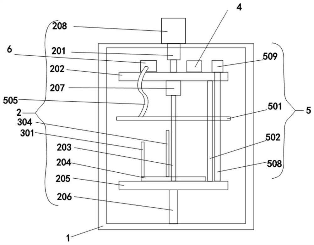
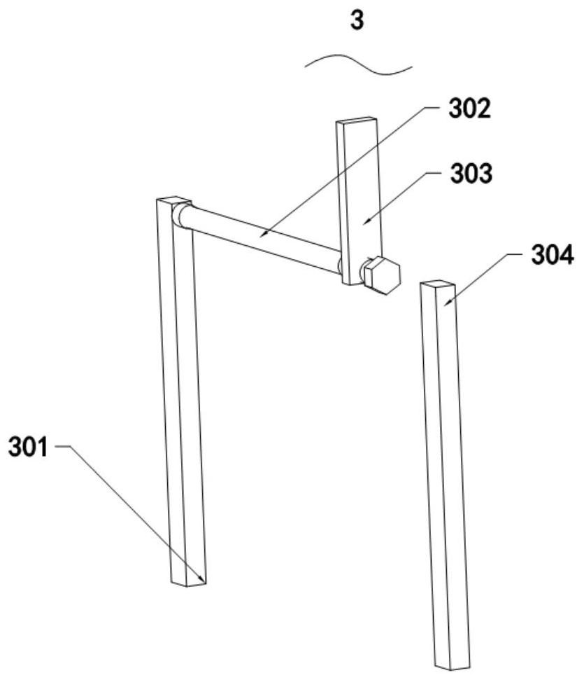
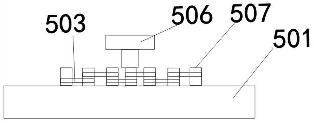
[0026] refer to Figure 1-6 As shown, an automatic cleaning device for condensing equipment includes a cleaning chamber 1 , and a rotating mechanism 2 and a cleaning mechanism 5 are provided in the inner cavity of the cleaning chamber 1 .

[0027] The rotating mechanism 2 includes a top plate 202 and a bottom plate 205. The top of the bottom plate 205 is provided with a placement plate 204. The placement plate 204 is rotatably connected to the bottom plate 205. The placement plate 204 is provided with a connecting column 203 that runs through the placement plate 204. The connecting column 203 and t...


PUM


Abstract

The invention relates to the technical field of condensers, in particular to an automatic cleaning device of condensing equipment. The automatic cleaning device comprises a cleaning bin, wherein a rotating mechanism and a cleaning mechanism are arranged in an inner cavity of the cleaning bin, and the rotating mechanism comprises a top plate and a bottom plate; a placing plate is arranged at the top of the bottom plate, the placing plate is rotatably connected with the bottom plate, and the placing plate is provided with a connecting column penetrating through the placing plate; the connecting column is fixedly connected with the placing plate, one end of the connecting column is fixedly connected with the bottom of the top plate through a third motor; the top of the top plate is in transmission connection with one end of an extension section of an output shaft of a first motor through a shaft rod; and the other end of the connecting column is fixedly connected with the top of the bottom plate. On the premise that it is guaranteed that water flow sprayed out of a steering spray head is always kept perpendicular to the plane of a radiator, all-directional cleaning of radiator fins is achieved, therefore, the situation that the water flow sprayed out of the steering spray head laterally impacts the radiator fins, and the radiator fins are permanently deformed in an unrecoverable manner is avoided.

Description

technical field [0001] The invention relates to the technical field of condensers, in particular to an automatic cleaning device for condensing equipment. Background technique [0002] Condenser, a component of a refrigeration system, is a type of heat exchanger that can convert gas or vapor into liquid, and transfer the heat in the tube to the air near the tube in a very fast manner. The working process of the condenser is an exothermic process, so the temperature of the condenser is relatively high. However, in the long-term operation of the condenser in the prior art, a large amount of dust and metal powder in the air will be adsorbed on the surface, so it is necessary to remove the condenser regularly for cleaning. The existing automatic cleaning device for condensing equipment, although The dust on the surface of the condenser can be cleaned, but it is easy to form an impact on the radiator fins during the cleaning process, resulting in deformation of the radiator fins...

Claims


Application Information

Patent Timeline
IPC IPC(8): F28G9/00F28G15/00F28G15/02F28G15/04F26B5/08
CPCF28G9/00F28G15/00F28G15/02F28G15/04F26B5/08F28G2015/006
Inventor 王国洪
Owner 义乌市今朝创意设计有限公司
Why Eureka
Try Eureka