Method for simulating dynamic fate distribution of pollutants in reclaimed water replenishment lake

A technology for reclaiming water and pollutants, applied in the directions of instrumentation, design optimization/simulation, calculation, etc., which can solve problems such as disregarding spatial specificity, low resolution of large-scale models, and inapplicable pollutant fate.

Pending Publication Date: 2021-11-30
TIANJIN CHENGJIAN UNIV +2
View PDF0 Cites 0 Cited by
  • Summary
  • Abstract
  • Description
  • Claims
  • Application Information

AI Technical Summary

Problems solved by technology

Traditional lake multi-media models are usually based on the assumption that the medium is completely mixed, and the physicochemical properties of each part of the medium are exactly the same, without considering the spatial specificity caused by source discharge and hydrodynamics. However, in the scenario of reclaimed water recharging a

Method used


Image

  • Method for simulating dynamic fate distribution of pollutants in reclaimed water replenishment lake
  • Method for simulating dynamic fate distribution of pollutants in reclaimed water replenishment lake
  • Method for simulating dynamic fate distribution of pollutants in reclaimed water replenishment lake

Examples


Embodiment 1

[0075] Sample collection and determination method used in the present invention

[0076] 1.1 Sample collection

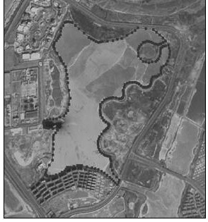
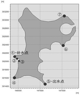
[0077] Taking Tianjin J Lake as the research object, such as figure 2 As shown, 7 sampling locations were determined according to the actual situation on site, as shown in image 3 As shown, the water sample sampling points are named W-1 (water supply port), W-2, W-3, W-4, W-5 (water outlet), W-6, W-7, and the sediment sampling points are named For S-2, S-3, S-4, S-5 (water outlet), S-6 and S-7, take 1.5L water samples from each sampling point and put them in clean brown glass bottles. Samples were collected with a stainless steel grab bucket, transferred to a clean tin foil bag, and stored in a refrigerator at 4°C. The concentration of pollutants detected by W-1 is used as the input data of the model, and the concentration data of other points are used to verify the accuracy of the model.

[0078] 1.2 Sample concentration detection

[0079] Water and sediment...

Embodiment 2

[0086] Coupling calculation of hydrodynamic and fugacity models

[0087] 2.1 Simulation results of lake hydrodynamics

[0088] MIKE 21 is used to establish the hydrodynamic model, the simulation step is 1 day, and the simulation time is 90 days; the flow direction of the study area is as follows: Image 6 shown. The flow velocity in the study area is as Figure 7 As shown, it is 2.09×10 -7 ~0.02 m / s, the flow velocity near the water supply point and the water outlet point is slightly higher, about 0.01~0.02 m / s, other areas, especially the boundary, the flow velocity is very slow, there are dead water areas, which is consistent with the actual situation of the lake.

[0089] 2.2 Detection of the effectiveness and accuracy of the method of the present invention

[0090] The measured value of DBP concentration in the lake water and sediment was compared with the simulated value of the model, respectively as follows: Figure 8 and Figure 9 shown. In the water phase, from ...


PUM


Abstract

The invention discloses a method for simulating dynamic fate distribution of pollutants in a reclaimed water replenishment lake. The method comprises the following steps: (1) establishing a terrain database; (2) establishing a hydrodynamic model; (3) establishing a fugacity model; and (4) coupling the model. The method for simulating the dynamic fate of the organic matters in the reclaimed water replenishment lake has the positive effects that the real scene of the reclaimed water replenishment lake can be simulated, and the time and space differentiation characteristics of the fate of the organic matters in an environmental system in the process of replenishing the reclaimed water to the lake can be accurately described; and a reliable theoretical basis can be provided for scientific supply of reclaimed water and effective control of pollutants.

Description

technical field [0001] The invention belongs to the technical field of safe utilization of regenerated water and simulation of migration and fate of organic pollutants in lakes, and in particular relates to a method for simulating the time-space migration and fate distribution of organic pollutants in the process of recharging lakes with reclaimed water. Background technique [0002] Reclaimed water, as an important source of ecological replenishment water for rivers and lakes, has effectively alleviated the urban ecological water crisis. However, due to the complexity of raw water quality and the limitations of treatment processes in reclaimed water, it contains a large number of micro-pollutants, which can enter the water environment through river and lake replenishment. in various media, and then affect the safety and health of the aquatic ecosystem. Therefore, determining the environmental fate of pollutants after entering the lake with reclaimed water recharge is partic...

Claims


Application Information

Patent Timeline
IPC IPC(8): G06F30/28G06F113/08G06F119/14
CPCG06F30/28G06F2113/08G06F2119/14
Inventor 王晨晨黄盼盼邱春生李静郭亚琦翟洪艳彭森田一梅冯涛白金超路明利
Owner TIANJIN CHENGJIAN UNIV
Why Eureka
Try Eureka