Supercharge Your Innovation With Domain-Expert AI Agents!

Camera module and imaging control method

A camera module and imaging control technology, which is applied in the field of cameras, can solve problems such as difficulty in achieving expectations in imaging effects, difficulty in miniaturization, and complex structure, and achieve the goals of improving sensory resolution, reducing image quality loss, and improving image sharpness Effect

Pending Publication Date: 2021-11-30
盛泰光电科技股份有限公司
View PDF3 Cites 0 Cited by
  • Summary
  • Abstract
  • Description
  • Claims
  • Application Information

AI Technical Summary

Problems solved by technology

However, the above-mentioned methods all need to increase the structural size of the existing camera module, or add another device to the body to achieve the desired effect, resulting in a complex overall structure of the camera module, large size, and difficulty in miniaturization. , the imaging effect is also difficult to meet expectations

Method used


Image

  • Camera module and imaging control method
  • Camera module and imaging control method

Examples


Embodiment

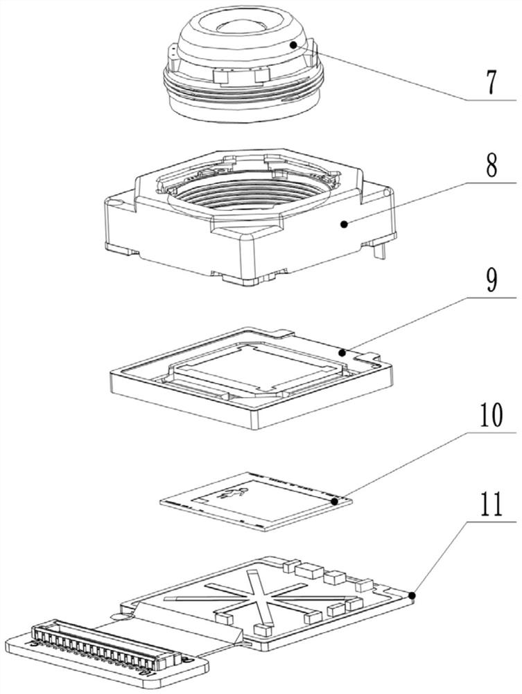
[0035] A camera module, basically figure 1 As shown: including the lens 7, the mirror 8, and the PCBA plate 11 sequentially provided, and a photosensitive chip 10 is provided on the PCBA plate 11. Among them, the photosensitive chip 10 on the lens 7, the mirror 8, and the PCBA plate 11, and the photosensitive chip 10 on the PCBA plate 11 are conventional setup structures of the existing camera modules, and the scheme is not improved, so the structure is not specifically described.

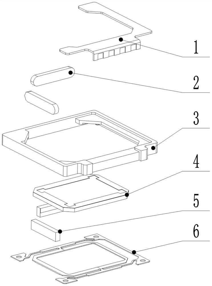
[0036] like figure 2 As shown, the mirror 8 and the photosensitive chip 10 are also provided with a gammell assembly 9 including a base bracket 3, a filter 4, and an actuating motor that are in the middle of the base bracket 3. Wide slots, the filter 4 is disposed in the pass slot and is paired with the photosensitive chip 10, the actuation motor mounting between the passage side wall and the filter 4 and electrically connects the PCBA plate 11. Used to move the filter 4 toward the specified direction ...

specific Embodiment approach

[0050] Predetermined driving waveform is input to the actuator motor in the first coil and the second coil, and shaking off setting time has elapsed, the time waveform by combining the control to a fixed frequency of 50Hz or 60Hz moved accurately jitter beam few microns, the galvanometer will shake the filter assembly is tilted to a certain angle, to complete the operation set specifies a first operation a, retention time at an angle, to complete the first image frame collected by the light-sensitive chip. Then after setting the switching time of the operation, the waveform changes at a fixed frequency of 50Hz or 60Hz of a few microns moving the beam jitter precisely, the galvanometer will shake the filter assembly is inclined at an angle to the other, to complete the specified action the second set of actions B, retention time at an angle, to complete the second image frame collected by the sensor chip, and then continue the cycle, the third frame image capture, the fourth frame ...


PUM


Abstract

The invention relates to the technical field of cameras, in particular to a camera module and an imaging control method.The camera module comprises a lens, a lens base and a PCBA board which are arranged in sequence, a photosensitive chip is arranged on the PCBA board, a galvanometer assembly is further arranged between the lens base and the photosensitive chip, the galvanometer assembly comprises a base support, an optical filter and an actuating motor, A through groove is formed in the middle of the base support, the optical filter is arranged in the through groove and right faces and is parallel to the photosensitive chip, and the actuating motor is installed between the side wall of the through groove and the optical filter, electrically connected with the PCBA board and used for driving the optical filter to shake and incline in the designated direction and reach the set angle when different sine wave currents pass through. Compared with an existing camera module, the camera module is simple in structure and good in imaging effect.

Description

Technical field [0001] The present invention relates to the field of camera, and more particularly to a camera module and an imaging control method. Background technique [0002] At present, the camera has been widely used in mobile phones, tablets, notebooks, security, car, medical, monitoring and other fields. There are different needs in different applications, such as: mobile phone cameras and other consumption fields require small size, and to photos Quality demand is constantly improving. In the non-mobile field, the requirements for the camera are modular output, and it is desirable that the camera module itself can process the basic information required for some platforms. But the ultimate purpose of anti-shake effect is also to improve the quality of the photo taken. [0003] Nowadays, there has been an anti-shake effect in the market, and there is also an anti-shake effect in the shift camera module, and the anti-shake effect is also an essential to improve the photo qu...

Claims


Application Information

Patent Timeline
IPC IPC(8): H04N5/225H04N5/265G06T3/40G02B7/00G03B17/12
CPCH04N5/265G06T3/4053G02B7/006G03B17/12H04N23/55
Inventor 陈泽清张伟张昊徐淦洲刘万山周得意
Owner 盛泰光电科技股份有限公司
Features
  • R&D
  • Intellectual Property
  • Life Sciences
  • Materials
  • Tech Scout
  • Unparalleled Data Quality
  • Higher Quality Content
  • 60% Fewer Hallucinations
Learn More