Emergency connection equipment for standby part and wiring terminal of network converter
A technology for connecting terminals and connecting equipment, which is applied in the direction of electrical components, selection devices, cooling/ventilation/heating transformation, etc. It can solve the problems of slow speed, low degree of automation, low efficiency, etc., to reduce the failure rate, quickly restore the network, The effect of increasing speed
- Summary
- Abstract
- Description
- Claims
- Application Information
AI Technical Summary
Problems solved by technology
Method used
Image
Examples
Embodiment 1
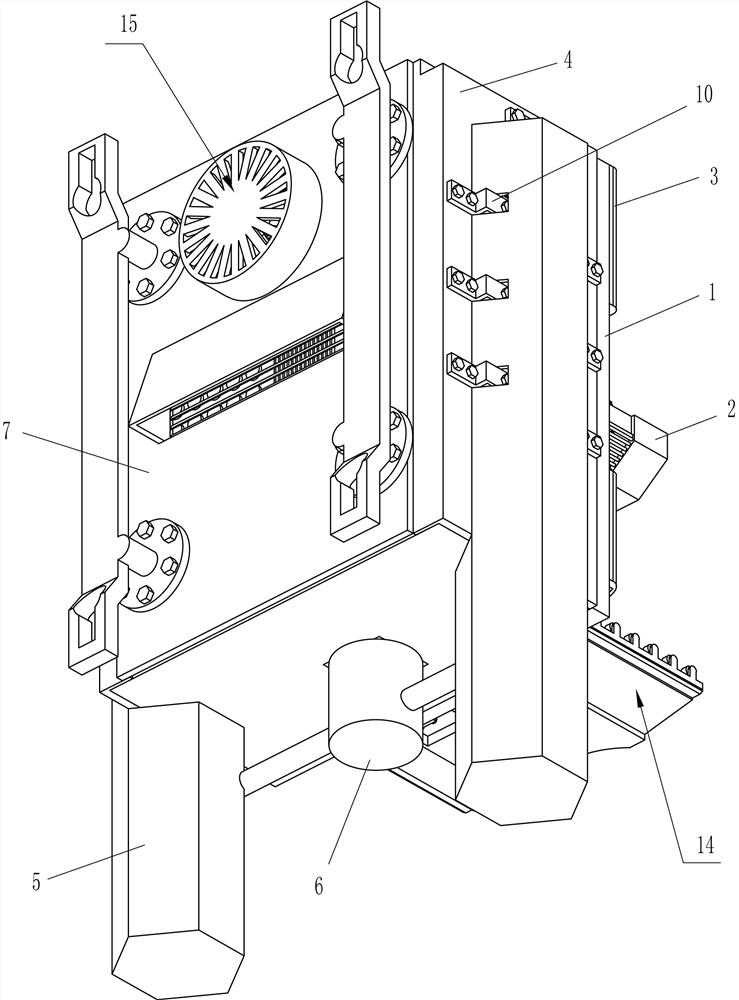
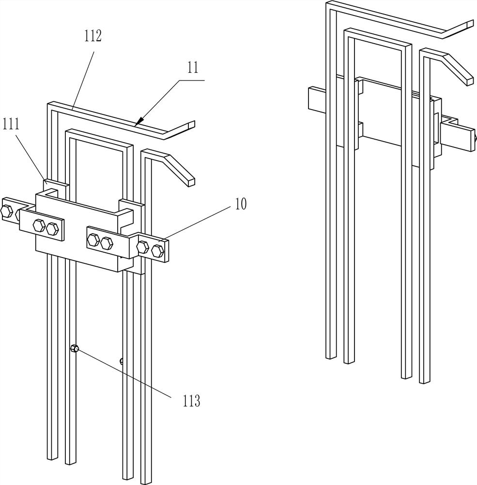
[0046] like Figure 1-11 As shown, an emergency connection device for network converter spare parts and terminal blocks, including a panel layer 1, a support frame 2, a trap door 3, a central plate layer 4, a surrounding frame 5, a connecting frame 6, and a hanging plate layer 7 , propulsion device 8, wiring device 9, fixed mount 10, guide device 11, loading device 12 and traveling device 13, specifically:
[0047] The middle part of the front side of the panel layer 1 is provided with a support frame 2. The panel layer 1 is a structure with openings on the upper and lower sides. The upper and lower positions of the front side of the panel layer 1 are provided with trapdoors 3, and the trapdoors 3 respectively block adjacent panels. The opening structure on the layer 1, the rear side of the panel layer 1 is provided with a central ply 4, the left and right sides of the central ply 4 are provided with surrounding frames 5, and the lower sides of the surrounding frames 5 are pro...
Embodiment 2
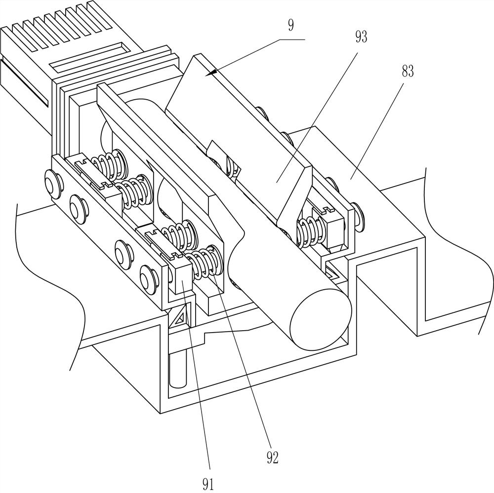
[0050] like Figure 12-26 As shown, the propulsion device 8 includes a first mobile pair 81, a first electric slide rail 82 and a propulsion frame 83, specifically:
[0051] The upper side of the support frame 2 is provided with a first mobile pair 81, and the position on the side of the support frame 2 near the first mobile pair 81 is provided with a first electric slide rail 82. A propelling frame 83 is arranged between the upper sides of the moving parts, and the wiring device 9 is arranged on the upper side of the propelling frame 83 .
[0052] When the above-mentioned embodiment is in operation, when the start switch is activated, the first electric slide rail 82 will drive its moving part to move backward, thereby driving the propulsion frame 83 to move to the rear side; An electric slide rail 82 will drive its moving parts to move forward, thereby driving the propulsion frame 83 to move forward. The control of the control box 16 is moved to the rear side again.
[00...
PUM
 Abstract
Description
Claims
Application Information
 - R&D
- Intellectual Property
- Life Sciences
- Materials
- Tech Scout
- Unparalleled Data Quality
- Higher Quality Content
- 60% Fewer Hallucinations
Browse by: Latest US Patents, China's latest patents, Technical Efficacy Thesaurus, Application Domain, Technology Topic, Popular Technical Reports.
© 2025 PatSnap. All rights reserved.Legal|Privacy policy|Modern Slavery Act Transparency Statement|Sitemap|About US| Contact US: help@patsnap.com


