Telescopic pressing nail capable of being positioned

A telescopic, limit block technology, applied in the direction of cooling/ventilation/heating transformation, can solve the problems of increasing the board space, easily touching the components on the board, and device damage, so as to avoid damage.

Active Publication Date: 2021-11-30
INSPUR SUZHOU INTELLIGENT TECH CO LTD
View PDF3 Cites 0 Cited by
  • Summary
  • Abstract
  • Description
  • Claims
  • Application Information

AI Technical Summary

Problems solved by technology

[0002] In the server field, some boards need to install heat sinks above the chip. The existing heat sink installation technology is to blindly install the heat sink from the top of the chip to the bottom, and then press the push pin to the corresponding opening on the board end. like figure 1 As shown, a spring is set on the outside of the pressing nail. In the initial state, the extrusion head at the lower part of the pressing nail is under the elastic force of the spring. The output part is too short, so that when the bottom surface of the heat sink touches the upper surface of the chip, the lower end of the extrusion head cannot extend into the board hole of the PCB, and thus the positioning effect cannot be achieved. It is necessary to manually adjust the position of the nail for many times and press it tentatively Press the nail to accurately insert into the hole
This operation method is easy to touch the components on the board, causing damage to the components
Generally, the positioning effect can also be achieved by simply extending the length of the extrusion head, but this will increase the space between the board and the bottom of the tray. Due to the limitation of the server design space, this solution has great limitations

Method used


Image

  • Telescopic pressing nail capable of being positioned
  • Telescopic pressing nail capable of being positioned
  • Telescopic pressing nail capable of being positioned

Examples


Embodiment 1

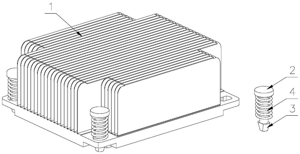
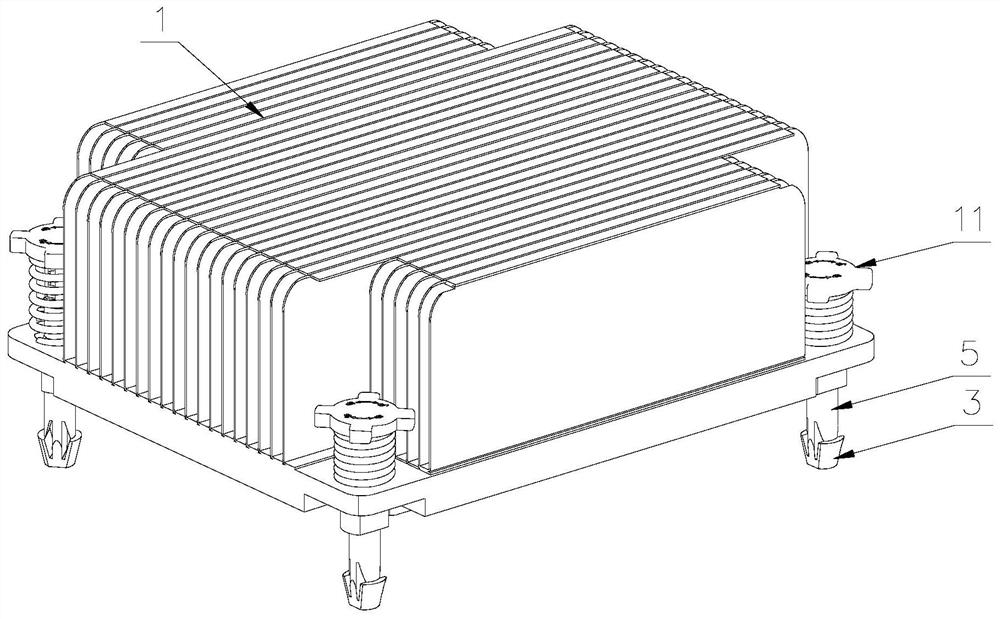
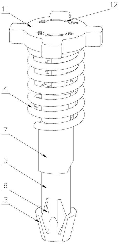
[0038] Such as Figure 2-4 , Figure 7 As shown, a positionable telescopic push nail includes an insertion rod 5, the lower end of the insertion rod 5 is provided with an extrusion head 3 for guiding and locking with the PCB hole, and the upper end of the insertion rod 5 is provided with The first limit block 9, the outer side of the upper part of the insertion rod 5 is provided with a column cover 13, the column cover 13 is a hollow cylindrical structure, and the upper part of the column cover 13 is provided with a screw cap 11, which is convenient for the column cover 13 to rotate and lock When force is applied, a number of first slideways 14 are provided on the side wall of the column sleeve 13, and the first stop block 9 is engaged in the first slideway 14 with a gap, and the upper end of the first slideway 14 runs through A first horizontal engaging portion 15 is connected to the ground, and the first horizontal engaging portion 15 is vertically arranged with the first s...

Embodiment 2

[0049] The difference from Example 1 is that, as Figure 5-6 As shown, in this embodiment, the spring 4 is arranged inside the column sleeve 13, and the lower end of the spring 4 is connected to the top of the insertion rod 5; the spring 4 is hidden inside the column sleeve 13 to strengthen the push button aesthetics, and avoid the influence of the spring 4 on the internal circuit of the server.


PUM


Abstract

The present invention discloses a telescopic pressing nail capable of being positioned. An extrusion head is arranged at the lower end of an insertion rod, a first limiting block is arranged at the upper end of the insertion rod, a column sleeve is arranged on the outer side of the upper portion of the insertion rod in a sleeving mode, a plurality of first sliding ways are arranged on the side wall of the column sleeve, and the upper ends of the first sliding ways are connected with first horizontal clamping parts in a penetrating mode; and a spring is arranged on one side of the inserting rod, and the upper end of the spring is connected with the turncap. In an initial state, the spring is not compressed, the extrusion head at the lower end of the insertion rod extends out towards the bottom to the maximum extent, when the cooling fin is installed downwards, the extrusion head firstly makes contact with a board clamping hole for alignment, and at the moment, the turncap is pressed downwards until the extrusion head of the insertion rod penetrates through the board clamping hole of the PCB; and the first limiting block is clamped in the first horizontal clamping part for locking by rotating the turncap, so that the lower space of the PCB is ensured, the positioning effect of the pressing nail is realized, and components on the board card are prevented from being damaged when the radiating fin is installed.

Description

technical field [0001] The invention belongs to the technical field of radiating fin assembly, and in particular relates to a positionable telescopic pressing nail. Background technique [0002] In the server field, some boards need to install heat sinks above the chip. The existing heat sink installation technology is to blindly install the heat sink from the top of the chip to the bottom, and then press the push pin to the corresponding opening on the board end. Such as figure 1 As shown, a spring is set on the outside of the pressing nail. In the initial state, the extrusion head at the lower part of the pressing nail is under the elastic force of the spring. The output part is too short, so that when the bottom surface of the heat sink touches the upper surface of the chip, the lower end of the extrusion head cannot extend into the board hole of the PCB, and thus the positioning effect cannot be achieved. It is necessary to manually adjust the position of the nail for m...

Claims


Application Information

Patent Timeline
Patent Type & Authority Applications(China)
IPC IPC(8): H05K7/20
CPCH05K7/20709
Inventor 甄兆辉曹真才
Owner INSPUR SUZHOU INTELLIGENT TECH CO LTD
Why Eureka
Try Eureka