
Automatic shell stamping device for electronic product machining

A technology of electronic products and stamping devices, which is applied in the field of automatic stamping devices for electronic product processing, can solve the problems of low automation, high equipment cost, increased labor costs, etc., and achieve the effect of high automation

Active Publication Date: 2021-12-03
南通迪贝德精密电子有限公司
View PDF5 Cites 0 Cited by
  • Summary
  • Abstract
  • Description
  • Claims
  • Application Information

AI Technical Summary

Problems solved by technology

[0003] However, most of the existing electronic product casing stamping and forming devices are manually loaded and unloaded, which has low processing efficiency, increases labor costs, and has a low degree of automation. However, some automated stamping equipment mostly cooperates with more electric equipment, resulting in a complex structure of the device. , the processing steps are cumbersome, the energy consumption is high, the later maintenance is also troublesome, and the cost of the equipment is high

Method used


Image

  • Automatic shell stamping device for electronic product machining
  • Automatic shell stamping device for electronic product machining
  • Automatic shell stamping device for electronic product machining

Examples


Embodiment 1

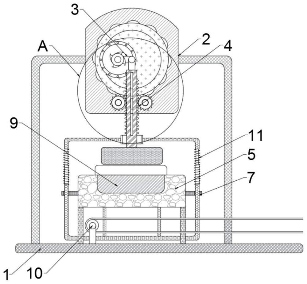
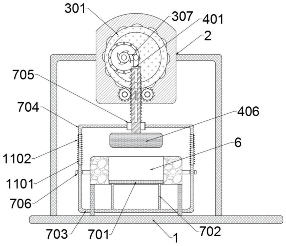
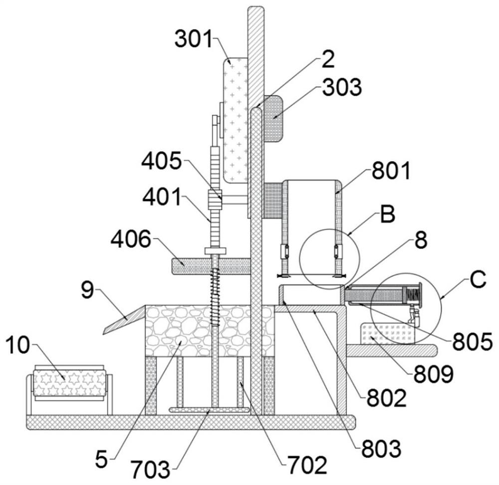
[0030] Example 1: Please refer to Figure 1-7 , an automatic stamping device for electronic product processing, including a processing table 1, a driving mechanism 3 is installed on the processing table 1 through a mounting frame 2, a stamping mechanism 4 is connected to the driving mechanism 3, and a forming block is fixedly installed on the processing table 1 5. There is a stamping groove 6 on the forming block 5, the stamping groove 6 is transparent from top to bottom, a blanking mechanism 7 is installed in the stamping groove 6, the blanking mechanism 7 is connected with the stamping mechanism 4, and a loading mechanism is installed on the rear side of the forming block 5 8. A blanking plate 9 is installed on the front side of the forming block 5, and a conveyor belt 10 is arranged below the blanking plate 9.

[0031] The driving mechanism 3 includes a ring-shaped installation frame 301, and the inner side of the installation frame 301 is evenly distributed with an annular...

Embodiment 2

[0041] Example 2: Please refer to Figure 1-7 , an automatic stamping device for electronic product processing, including a processing table 1, a driving mechanism 3 is installed on the processing table 1 through a mounting frame 2, a stamping mechanism 4 is connected to the driving mechanism 3, and a forming block is fixedly installed on the processing table 1 5. There is a stamping groove 6 on the forming block 5, the stamping groove 6 is transparent from top to bottom, a blanking mechanism 7 is installed in the stamping groove 6, the blanking mechanism 7 is connected with the stamping mechanism 4, and a loading mechanism is installed on the rear side of the forming block 5 8. A blanking plate 9 is installed on the front side of the forming block 5, and a conveyor belt 10 is arranged below the blanking plate 9.

[0042] The driving mechanism 3 includes a ring-shaped installation frame 301, and the inner side of the installation frame 301 is evenly distributed with an annular...


PUM


Abstract

The invention relates to the technical field of electronic product machining, and discloses an automatic shell stamping device for electronic product machining. The device comprises a machining table, a driving mechanism is mounted on the machining table through a mounting frame, a stamping mechanism is connected to the driving mechanism, a forming block is fixedly mounted on the machining table, a stamping groove is formed in the forming block, the stamping groove is vertically through, a discharging mechanism is installed in the stamping groove and connected with the stamping mechanism, a feeding mechanism is installed on the rear side of the forming block, a discharging plate is installed on the front side of the forming block, and a conveying belt is arranged below the discharging plate. The stamping mechanism is driven by the driving mechanism to do intermittent motion, so that a stamping block in the stamping mechanism automatically stamps an electronic product shell, meanwhile, the arranged discharging device is matched with the feeding device to automatically perform feeding and discharging operation on a stamped and formed product, the automation degree is high, operation is convenient, and the machining efficiency is improved.

Description

technical field [0001] The invention relates to the technical field of electronic product processing, in particular to an automatic stamping device for electronic product processing shells. Background technique [0002] Electronic products are related products based on electric energy, mainly including: watches, smart phones, telephones, televisions, DVD players, video recorders, camcorders, radios, tape recorders, combination speakers, CD players, computers, mobile communication products, etc. etc. When processing electronic products, it is necessary to perform stamping and forming operations on the shells of electronic products. [0003] However, most of the existing electronic product casing stamping and forming devices are manually loaded and unloaded, which has low processing efficiency, increases labor costs, and has a low degree of automation. However, some automated stamping equipment mostly cooperates with more electric equipment, resulting in a complex structure of...

Claims


Application Information

Patent Timeline
Patent Type & Authority Applications(China)
IPC IPC(8): B21D22/02B21D43/04B21D45/04
CPCB21D22/02B21D43/04B21D45/04Y02P70/10
Inventor 莫家豪
Owner 南通迪贝德精密电子有限公司
Features
  • Generate Ideas
  • Intellectual Property
  • Life Sciences
  • Materials
  • Tech Scout
  • Unparalleled Data Quality
  • Higher Quality Content
  • 60% Fewer Hallucinations
Learn More