
Automatic finned tube feeding and discharging device

A technology of automatic loading and unloading and finned tubes, applied in storage devices, feeding devices, positioning devices, etc., can solve problems such as bending and deformation of copper tubes, affecting the shape of copper tubes, and wear of finned tubes to achieve weight reduction, The effect of simple structure

Active Publication Date: 2021-12-03
TAIZHOU CHIJUN INTELLIGENT EQUIP CO LTD
View PDF7 Cites 0 Cited by
  • Summary
  • Abstract
  • Description
  • Claims
  • Application Information

AI Technical Summary

Problems solved by technology

[0003] 1. There is a large-scale pipe pressing mechanism on the feeding frame, and the pipes are arranged on the heavy-duty overall shelf. When the equipment is running, due to the heavy equipment and the high-speed rotation of the pipe during processing, the entire support frame shakes
[0004] 2. In the feeding mechanism, the cylinder is driven against the pipe, and the driving wheel is conveyed through the grinding wheel slipping mechanism. In addition, there is resistance in the copper pipe itself, and the outside of the finned pipe causes wear and tear, which affects the shape of the copper pipe.
[0005] 3. There is a long distance between the feeding frame, the jacking cylinder mechanism, the centering mechanism, the feeding mechanism and the finned tube tooth forming mechanism. The processing head is far away, and the pipe is in a long-distance suspended state. The electric bending degree of medium copper pipe is large, causing the copper pipe to bend and deform
[0006] 4. Since the copper tube needs to be soaked in the coolant after processing, the coolant provided in the feeding mechanism will be brought into the material box together with the tube, making it difficult to discharge the liquid

Method used


Image

  • Automatic finned tube feeding and discharging device
  • Automatic finned tube feeding and discharging device
  • Automatic finned tube feeding and discharging device

Examples


Embodiment Construction

[0035] To unify technical terms, embodiments of the present invention are described in detail below, examples of which are shown in the drawings, wherein the same or similar reference numerals designate the same or similar elements or elements having the same or similar functions throughout. The embodiments described below by referring to the figures are exemplary only for explaining the present invention and should not be construed as limiting the present invention.

[0036] In the description of the present invention, it should be understood that the orientations or positional relationships indicated by the terms "center", "upper", "lower", "front", "rear", "left", "right" etc. are based on the attached The orientation or positional relationship shown in the figure is only for the convenience of describing the present invention and simplifying the description, and does not indicate or imply that the referred combination or element must have a specific orientation, be construc...


PUM


Abstract

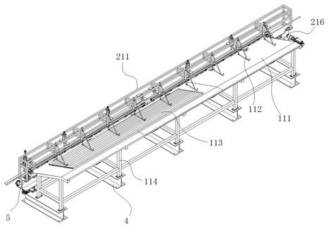
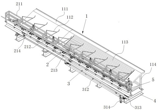
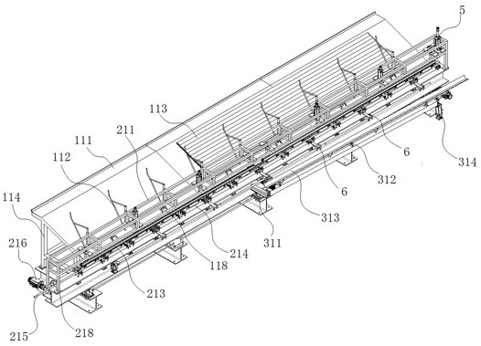
The invention discloses and provides an automatic finned tube feeding and discharging device which is composed of a tube pressing mechanism, a conveying forming mechanism and a discharging mechanism, the tube pressing mechanism comprises a material frame body, an upper pressing mechanism and tube bodies arranged in sequence, and the upper pressing mechanism is composed of a micro air cylinder, a pressing rod and a discharging fine adjustment structure; and the conveying forming mechanism comprises a supporting structural part, a conveying frame, an upper pressing roller, a lower supporting roller, a guide rod and a steel wire rope feeding mechanism, the steel wire rope feeding mechanism comprises a servo motor, a steel wire rope, an electromagnetic clutch and a driving wheel, the guide rod drives a tube body to do axial reciprocating motion, and the discharging mechanism comprises a turbine worm gear motor, a first bearing seat and a trough. The whole upper pressing mechanism is stable, can orderly discharge and feed materials, independently partitions tubes, and is simple in structure, light in weight, free of shaking, stable under clamping of rubber wheels and bearings, free of deformation of tubes and more convenient to return materials.

Description

technical field [0001] The invention relates to the technical field of automatic forming, in particular to an automatic loading and unloading device for finned tubes. Background technique [0002] At present, in the production process of the existing finned tube copper tube end forming thread, although the feeding, tube tooth forming and unloading are semi-automated, there are still some problems. Patent No. 2019110215375 is a complete set of efficient finned tube processing equipment. It involves a feeding frame, a jacking cylinder mechanism, a centering mechanism, a feeding mechanism, a finned tube tooth forming mechanism, a mandrel machine and a blanking rod. The machine is arranged sequentially along the same straight line, and the jacking cylinder mechanism, centering mechanism, and feeding mechanism are all arranged on the feeding frame. At present, the equipment has the following problems. [0003] 1. There is a large-scale pipe crimping mechanism on the feeding fram...

Claims


Application Information

Patent Timeline
Patent Type & Authority Applications(China)
IPC IPC(8): B21D43/00B21D43/02B21D43/08B21D43/14B21D43/16B21D45/06B21D37/16
CPCB21D43/006B21D43/003B21D43/026B21D43/08B21D43/145B21D43/16B21D45/06B21D37/16
Inventor 陈群施华林徐洪伟
Owner TAIZHOU CHIJUN INTELLIGENT EQUIP CO LTD
Features
  • Generate Ideas
  • Intellectual Property
  • Life Sciences
  • Materials
  • Tech Scout
  • Unparalleled Data Quality
  • Higher Quality Content
  • 60% Fewer Hallucinations
Learn More