Rotary welding and polishing device for intelligent manufacturing
A technology of spin welding and polishing devices, which is applied in the direction of manufacturing tools, grinding drive devices, grinding/polishing equipment, etc. It can solve the problems of rough surface of the welding place and affect physical and mental health, and achieve the effect of avoiding movement
- Summary
- Abstract
- Description
- Claims
- Application Information
AI Technical Summary
Problems solved by technology
Method used
Image
Examples
Embodiment 1
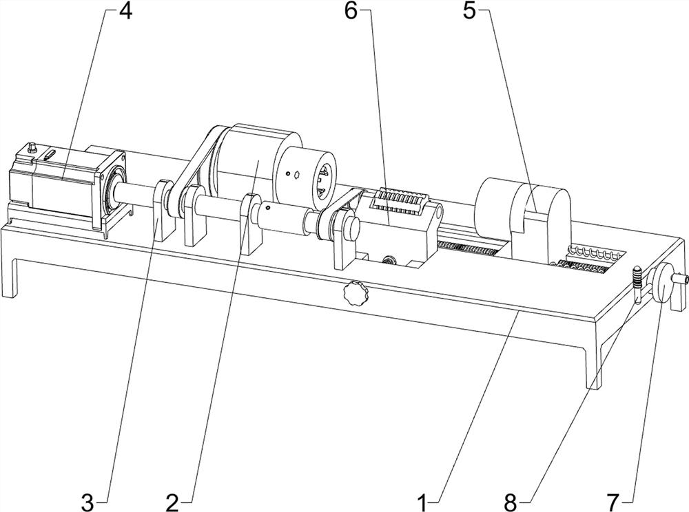
[0024] A spin welding polishing device for intelligent manufacturing, such as Figure 1-Figure 4 As shown, it includes a base 1, a support seat 2, a support plate 3, a rotating mechanism 4, and a fixing mechanism 5. The support seat 2 is fixedly connected to the rear part on the left side of the top of the base 1, and the support plate 3 is provided at intervals on the front side of the top of the base 1. A rotating mechanism 4 is provided between the base 1 , the support seat 2 and the support plate 3 , and a fixing mechanism 5 is provided on the support seat 2 .
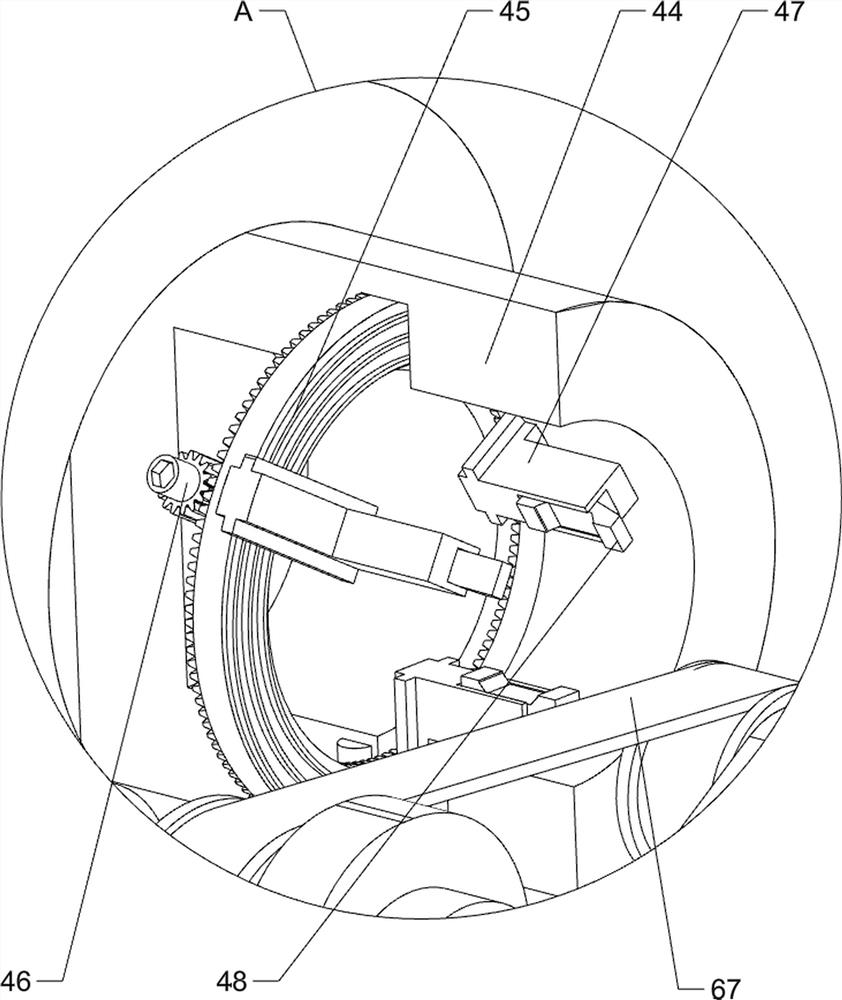
[0025] The rotating mechanism 4 includes a servo motor 41, a drive shaft 42, a first transmission assembly 43, a driven shaft 44, a locking toothed disc 45, a locking screw 46, a clamping claw 47 and a locking block 48. The top left of the base 1 A servo motor 41 is fixedly connected to the front side of the front part, and a driving shaft 42 is arranged on the upper part of the three support plates 3 on the left i...
Embodiment 2
[0029] On the basis of Example 1, such as Figure 1-Figure 4 As shown, a polishing mechanism 6 is also included, and the polishing mechanism 6 includes a transmission movable block 61, a locking spring 62, a positioning screw 63, a short transmission shaft 64, a positioning seat 65, an adjustment screw 66, a second transmission assembly 67 and a polishing wheel 68, the right part of drive shaft 42 is slidingly provided with a transmission movable block 61, and a locking spring 62 is fixedly connected between the inner surface of the transmission movable block 61 and the inside of the drive shaft 42, and the left part of the transmission movable block 61 is rotatably provided with two positioning The screw rod 63 and the positioning screw rod 63 are connected in rotation with the drive shaft 42, the upper part of the rightmost support plate 3 is rotatably provided with a transmission short shaft 64, the right side of the front part of the base 1 is slidingly provided with a posi...
Embodiment 3
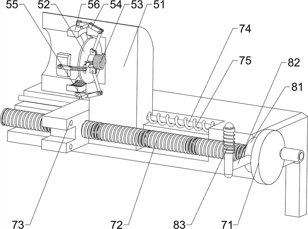
[0034] On the basis of embodiment 1 and embodiment 2, such as figure 1 and Figure 4 As shown, a locking mechanism 8 is also included, and the locking mechanism 8 includes a locking block 81, a fixed connecting rod 82 and an anti-skid grip 83, and the right part of the adjusting screw 72 is rotated in a circumferential direction and is provided with a locking block 81, and the front side of the locking block 81 Fixedly connected with a fixed connecting rod 82, the front end of the fixed connecting rod 82 is fixedly connected with a non-slip grip 83.
[0035] After the adjustment of the movable seat 51 is completed, the fixed connecting rod 82 can be pulled by the non-slip grip 83 to rotate, and the fixed connecting rod 82 drives the locking block 81 to rotate, and the locking block 81 rotates to limit the adjustment screw 72, so that the adjustment screw can be avoided. The lever 72 is swiveled.
PUM
 Abstract
Description
Claims
Application Information
 - R&D
- Intellectual Property
- Life Sciences
- Materials
- Tech Scout
- Unparalleled Data Quality
- Higher Quality Content
- 60% Fewer Hallucinations
Browse by: Latest US Patents, China's latest patents, Technical Efficacy Thesaurus, Application Domain, Technology Topic, Popular Technical Reports.
© 2025 PatSnap. All rights reserved.Legal|Privacy policy|Modern Slavery Act Transparency Statement|Sitemap|About US| Contact US: help@patsnap.com


