Continuous production device for producing modified asphalt with ultrahigh viscosity and toughness

A modified asphalt and production device technology, applied in the field of asphalt production, can solve the problems of inability to realize efficient mixing and processing of asphalt, increasing demand for modified asphalt, affecting production efficiency, etc. Small footprint effect

Active Publication Date: 2021-12-03
山东高速建材集团有限公司 +3
View PDF5 Cites 1 Cited by
  • Summary
  • Abstract
  • Description
  • Claims
  • Application Information

AI Technical Summary

Problems solved by technology

With the acceleration of the urbanization process, the sharp increase in road traffic, the destruction of the early concrete pavement, and the need for major repairs, the demand for modified asphalt has increased, and the existing modified asphalt equipment consumes a lot of energy. The structure is complex and the floor area is large, so the efficient mixing and processing of asphalt cannot be realized, which affects the production efficiency

Method used


Image

  • Continuous production device for producing modified asphalt with ultrahigh viscosity and toughness
  • Continuous production device for producing modified asphalt with ultrahigh viscosity and toughness
  • Continuous production device for producing modified asphalt with ultrahigh viscosity and toughness

Examples


Embodiment 1

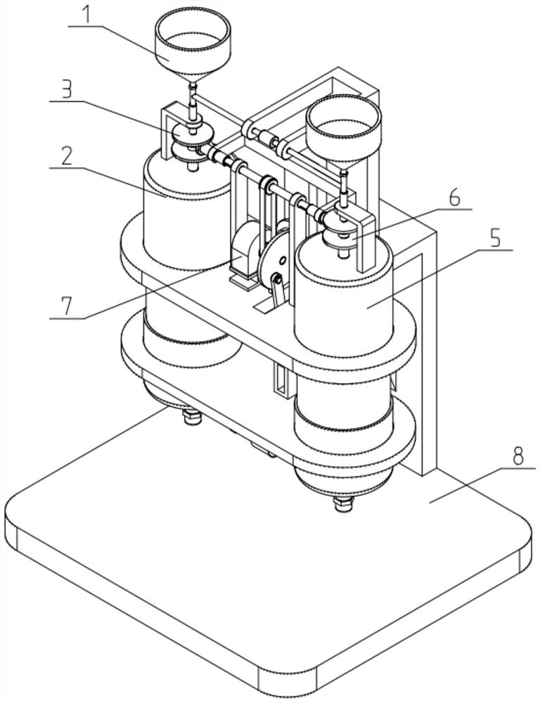
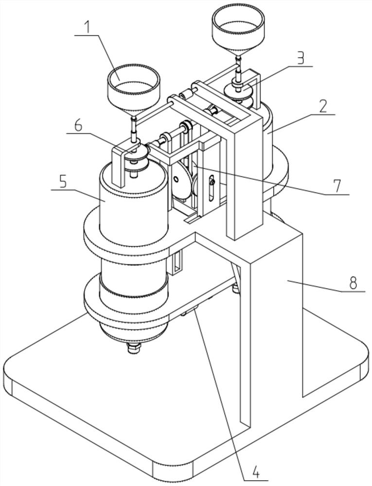
[0039] Such as Figure 1-12 As shown, a continuous production device for ultra-high viscosity and toughness modified asphalt production, including a feeding mechanism 1, a first reaction tank 2, a mixing mechanism 3, a feeding mechanism 4, a second reaction tank 5, and a shearing mechanism 6. The driving mechanism 7 and the stand 8; one end of the feeding mechanism 1 installed on the stand 8 is connected to the mixing mechanism 3, so as to guide the raw materials into the first reaction tank 2 through the mixing mechanism 3; The other end of mechanism 1 is connected with shearing mechanism 6, to guide raw material in the first reaction tank 2 by shearing mechanism 6; Material delivery mechanism 4 is connected with first reaction tank 2 and second reaction tank 5, to The raw materials are pumped into the second reaction tank 5 through the first reaction tank 2; a mixing mechanism 3 is installed in the first reaction tank 2 to mix and stir the raw materials in the first reaction...

Embodiment 2

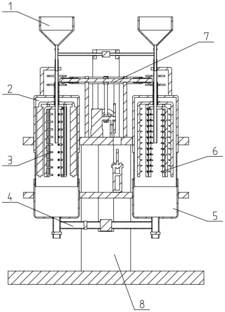
[0042] Such as Figure 1-12 As shown, the mixing mechanism 3 includes a first friction wheel 31, a second friction wheel 32, a first outer tube 33, a first inner tube 34, an inner stirring rod 35 and an outer stirring rod 36; the first friction wheel 31 is fixed On the first outer tube 33, the middle part of the first outer tube 33 is sealed and rotated on the top surface of the first reaction tank 2, and the second friction wheel 32 is fixed on the first inner tube 34, and the middle part of the first inner tube 34 is sealed and rotated at the second Inside an outer tube 33; the first outer tube 33 is positioned on the tube body of the first reaction tank 2 and surrounds and fixes a plurality of outer stirring rods 36; The stirring rod 35, the inner stirring rod 35 is located inside the outer stirring rod 36; the driving mechanism 7 is connected to the first friction wheel 31 and the second friction wheel 32; A stirring impeller is fixed on it.

[0043] After the drive mech...

Embodiment 3

[0047] Such as Figure 1-12 As shown, the feed mechanism 1 includes a feed hopper 11, a feed pipe 12 with a control valve and a horizontal feed pipe 13 with a pump; the feed hopper 11 and the feed pipe 12 are respectively provided with two, The two feeding hoppers 11 are fixedly connected with the two feeding pipes 12 one by one, and the two feeding pipes 12 are fixedly connected by a horizontal feeding pipe 13, which is located below the control valve; the horizontal feeding pipe 13 passes through the bracket It is fixed on the stand 8; one feeding tube 12 is sealed and moved in the first inner tube 34, and the other feeding tube 12 is sealed and moved in the second inner tube 64. When the feeding mechanism 1 is in use, the two feeding hoppers 11 can be used to feed materials respectively. When the asphalt mixture circulation process is required, the control valves of the two feeding pipes 12 are closed, and the horizontal feeding pipe 13 is turned off. The pump is turned on...


PUM


Abstract

The invention relates to the technical field of asphalt production, in particular to a continuous production device for producing modified asphalt with ultrahigh viscosity and toughness, which comprises a feeding mechanism, a first reaction tank, a mixing mechanism, a conveying mechanism, a second reaction tank, a shearing mechanism, a driving mechanism and a vertical frame, one end of the feeding mechanism mounted on the vertical frame is connected with the mixing and stirring mechanism, so that raw materials are guided and conveyed into the first reaction tank through the mixing and stirring mechanism; the other end of the feeding mechanism is connected with the shearing mechanism, so that raw materials are guided into the first reaction tank through the shearing mechanism; the material conveying mechanism is connected with the first reaction tank and the second reaction tank so as to pump the raw materials into the second reaction tank through the first reaction tank. The first reaction tank and the second reaction tank are arranged inside the asphalt mixing and emulsifying device, an asphalt mixture can be uniformly mixed and stirred through the mixing and stirring mechanism in the first reaction tank, the asphalt mixture can be sheared and emulsified through the shearing mechanism in the second reaction tank, and the mixing and processing effect of modified asphalt can be improved.

Description

technical field [0001] The invention relates to the technical field of asphalt production, and more specifically relates to a continuous production device for producing ultra-high viscosity and toughness modified asphalt. Background technique [0002] my country is currently in a high-speed development period of road construction, and more than 95% of new high-grade roads are asphalt roads every year. Modified asphalt concrete pavement is widely used in urban roads and expressways because of its excellent pavement performance. With the acceleration of the urbanization process, the sharp increase in road traffic, the destruction of the early concrete pavement, and the need for major repairs, the demand for modified asphalt has increased, and the existing modified asphalt equipment consumes a lot of energy. The structure is complex and the floor area is large, so the efficient mixing and processing of asphalt cannot be realized, which affects the production efficiency. Cont...

Claims


Application Information

Patent Timeline
Patent Type & Authority Applications(China)
IPC IPC(8): E01C19/10
CPCE01C19/10E01C19/1009E01C19/104
Inventor 张树文赵佃宝穆明浩张哲韩立斌李云飞郑君刘新强吕妍王峥李明杰李朝旭孙并臻毕海崧何宁何军李颖
Owner 山东高速建材集团有限公司
Why Eureka
Try Eureka