Offshore generator set base
A technology for generator sets and support seats, which is applied in the direction of engines, wind power generation, wind power engines, etc., can solve problems such as easy shaking, easy damage to generator components, and poor anti-dumping ability of the base, so as to achieve simple and convenient use and enhance anti-dumping ability , the effect of reducing the shaking amplitude
- Summary
- Abstract
- Description
- Claims
- Application Information
AI Technical Summary
Problems solved by technology
Method used
Image

Examples
Embodiment 1
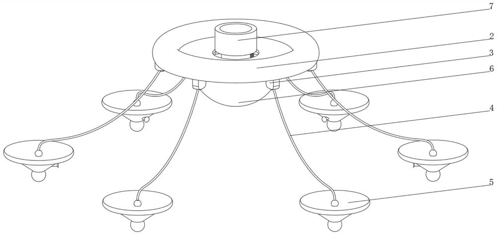
[0037] see Figure 1-2 , the present invention provides a technical solution: an offshore generating set base, specifically comprising:
[0038] A support seat 1, a floating ring 2 is provided on the top of the outer side of the support seat 1, and a fixed ear 3 fixed on the bottom of the floating ring 2, and the floating ring 2 is fixedly connected to the outer side of the support seat 1;
[0039] A dragline 4, one end of the dragline 4 is connected with an anti-dumping device 5, and the end of the dragline 4 away from the anti-dumping device 5 is fixedly connected with the fixed ear 3;
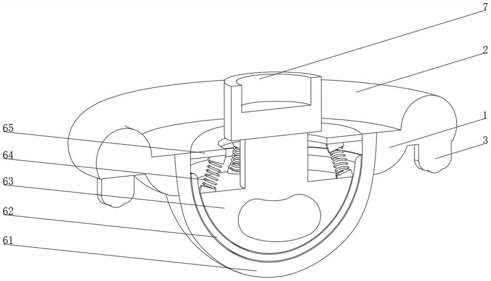
[0040] A buffer device 6, the buffer device 6 is arranged inside the support seat 1, and the top of the buffer device 6 is provided with a mounting seat 7;
[0041] Buffer device 6 comprises:
[0042] Buffer spherical shell 61, the inner wall of the buffer spherical shell 61 is provided with a rotating support 62, the interior of the rotating support 62 is provided with a rotating hemisphe...
Embodiment 2
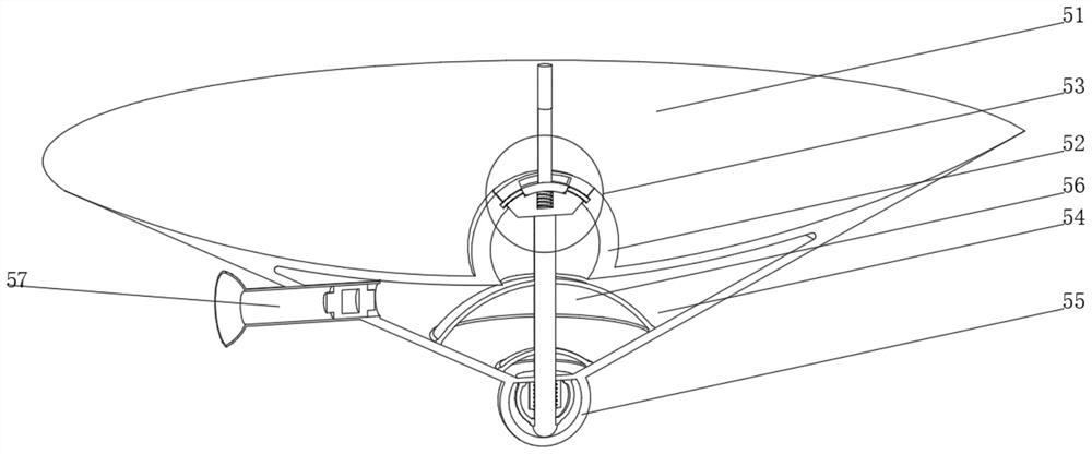
[0045] see Figure 1-3 On the basis of Embodiment 1, the present invention provides a technical solution: the anti-dumping device 5 includes a water blocking plate 51, a connecting spherical shell 52 is provided at the center of the top of the water blocking plate 51, and a control device 53 is provided on the inner wall of the connecting spherical shell 52 , the inside of the water blocking plate 51 is provided with a storage cavity 54, the top of the storage cavity 54 communicates with the connecting spherical shell 52, the bottom of the water blocking plate 51 is provided with a reset device 55, the inner wall of the storage cavity 54 stores the reticulated shell 56, and the storage cavity 54 One side is connected with an air outlet nozzle 57, the water blocking plate 51 is set in the shape of a trumpet with the opening facing upwards, the top of the control device 53 is connected with the cable 4, and the interior of the storage reticulated shell 56 is filled with metal sod...
Embodiment 3
[0048] see Figure 1-5 The present invention provides a technical solution on the basis of Embodiment 1 and Embodiment 2: the control device 53 includes a ball cover 531, a sliding cavity 532 is opened inside the ball cover 531, and a top block 533 is slidably connected to the inner wall of the sliding cavity 532 , the bottom of the top block 533 is provided with a return spring 534, and both sides of the sliding cavity 532 are provided with a sliding hole 535, the inner wall of the sliding hole 535 is connected with a clamping rod 536 through a spring column, and the ball cover 531 is arranged in the opening connecting the top of the spherical shell 52 , the opening of the connecting spherical shell 52 is provided with a card slot suitable for the clamp rod 536, the top of the top block 533 is fixedly connected with the cable 4, the reset device 55 includes a control spherical shell 551, and the top of the inner wall of the control spherical shell 551 passes through an arc Th...
PUM
 Abstract
Description
Claims
Application Information