Underground water layered monitoring device and method based on dilution method
A monitoring device and groundwater technology, applied in the direction of measuring devices, instruments, etc., can solve problems such as waste of exploration resources, and achieve the effects of avoiding mixed water sample sampling, improving accuracy, and avoiding eccentricity
- Summary
- Abstract
- Description
- Claims
- Application Information
AI Technical Summary
Problems solved by technology
Method used
Image
Examples
Embodiment 1
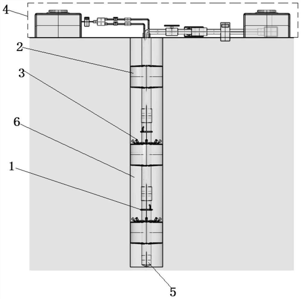
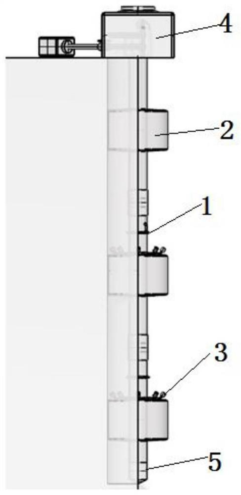
[0057] see figure 1 Or 2, this embodiment discloses a groundwater stratified monitoring device based on the dilution method, including a source system 1 , a stratified water isolation system 2 , an acquisition system 3 , a control system 4 and a counterweight 5 .
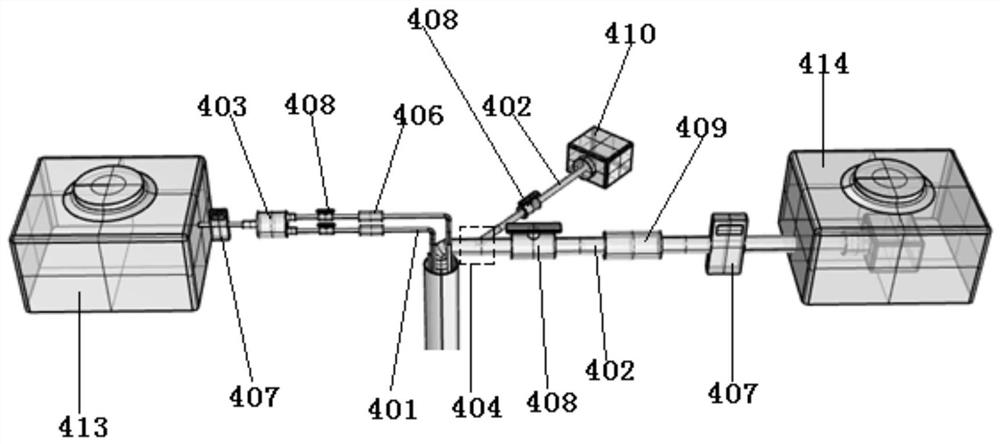
[0058] The control system 4 includes a surface feeding pipe 401 , a surface water conduit 402 , a feeding water tank 413 and a water injection tank 414 .
[0059] see image 3 The source water tank 413 and the water injection tank 414 are all arranged on the ground surface, and the source water pump is arranged inside the source water tank 413, and the source water pump is connected with the source tap 403 outside the source water tank 413 through a conduit. A digital pressure gauge 407 is installed on the conduit between the input and distribution joints 403 . The source water tank 413 is equipped with a tracer, the tracer is sodium chloride solution, and the purpose is to eliminate the temperature convection cau...
Embodiment 2
[0077] This embodiment discloses a groundwater stratified monitoring method based on the dilution method, based on the device described in Embodiment 1, comprising the following steps:
[0078] 1) According to the geological survey data, determine the spatial information of the relatively impermeable layer, and combine the thickness of the aquifer and the actual survey requirements to determine the position and quantity of the detected aquifer, and then determine the value of M.
[0079] 2) According to the position of the relative impermeable layer, determine the length of the conduit 2015 in each of the layered water barriers 201 to ensure that the subsequent layered water barriers 2011 can be accurately installed in the area of the relatively impermeable layer.
[0080] 3) Using N adapters 202 to connect M layered water barriers 201 together to form a layered water barrier system 2, the bottom end of the layered water barrier system 2 is connected to the counterweight 5, a...
Embodiment 3
[0092] see figure 1 Or 2, this embodiment discloses a groundwater stratified monitoring device based on the dilution method, including a source system 1 , a stratified water isolation system 2 , an acquisition system 3 , a control system 4 and a counterweight 5 .
[0093] The control system 4 includes a surface feeding pipe 401 , a surface water conduit 402 , a feeding water tank 413 and a water injection tank 414 .
[0094] see image 3 The source water tank 413 and the water injection tank 414 are all arranged on the ground surface, and the source water pump is arranged inside the source water tank 413, and the source water pump is connected with the source tap 403 outside the source water tank 413 through a conduit. A digital pressure gauge 407 is installed on the conduit between the input and distribution joints 403 .
[0095] The source distribution joint 403 is connected to M surface source pipes 401, and each surface source pipe 401 is equipped with a smart flow meter...
PUM
 Abstract
Description
Claims
Application Information
 - R&D
- Intellectual Property
- Life Sciences
- Materials
- Tech Scout
- Unparalleled Data Quality
- Higher Quality Content
- 60% Fewer Hallucinations
Browse by: Latest US Patents, China's latest patents, Technical Efficacy Thesaurus, Application Domain, Technology Topic, Popular Technical Reports.
© 2025 PatSnap. All rights reserved.Legal|Privacy policy|Modern Slavery Act Transparency Statement|Sitemap|About US| Contact US: help@patsnap.com


