Supercharge Your Innovation With Domain-Expert AI Agents!

Electric machine, in particular separately excited synchronous machine

A synchronous motor, contact element technology, applied in circuits, current collectors, electromechanical devices, etc., can solve problems such as strengthening and insufficient axial tension

Pending Publication Date: 2021-12-03
AUDI AG
View PDF4 Cites 0 Cited by
  • Summary
  • Abstract
  • Description
  • Claims
  • Application Information

AI Technical Summary

Problems solved by technology

If the axial tension is too weak, the arrangement is too prone to vibration due to too low a pressing force
Excessive wear if the axial pressing force is too strong
If the lateral pressing force is too low, this lateral tensioning will not serve its purpose, since tilting or wobbling can still occur with stronger excitation
If the contact force is too high, the surface of the contact element is pressed against the guide wall too much, so that increased friction and possible insufficient axial tensioning or guiding

Method used


Image

  • Electric machine, in particular separately excited synchronous machine
  • Electric machine, in particular separately excited synchronous machine
  • Electric machine, in particular separately excited synchronous machine

Examples


Embodiment Construction

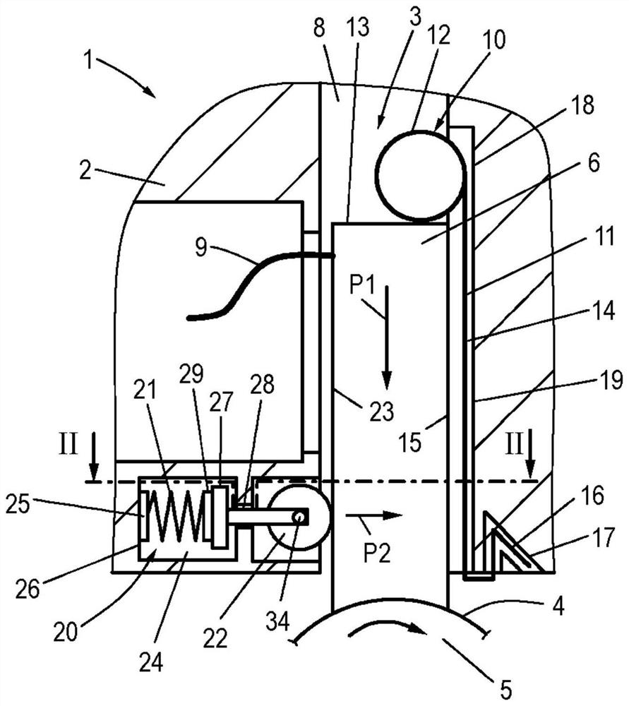
[0025] figure 1 A partial view of an electric machine 1 according to the invention is shown, which has a housing 2 in which a contact element arrangement 3 is arranged which makes electrical contact with a slip ring 4 of a rotor shaft 5 . For example, in the case of a separately excited synchronous machine, usually several, usually three, slip rings are arranged on the rotor shaft 5 , which are assigned to different phases and are in turn coupled to different conductor windings for generating the field field.

[0026] The contact element arrangement 3 has, on the one hand, contact elements 6 preferably in the form of carbon brushes. The contact element is here an elongated contact element 6 with a rectangular cross section, which has a groove-shaped geometry 7 on its underside corresponding to the geometry of the slip ring 4 rotating during operation, the contact element 6 is press fitted onto the slip ring. The contact element 6 is received in a guide 8 formed in the housin...


PUM


Abstract

The invention relates to an electric machine, in particular a separately excited synchronous machine, comprising: a rotor shaft (5) having at least one slip ring (4); and at least one electrically conductive contact element (6), in particular a carbon brush, resting on the slip ring (4), which is received in a channel-like guide (8) formed in the housing (2, 36) and extending radially with respect to the rotor shaft (5) and is tensioned radially with respect to the slip ring (4) by means of a spring element (10), a roller (22) is provided which is tensioned laterally relative to the contact element (6) by means of a further spring element (20), by means of which roller the contact element (6) is tensioned relative to the wall (19) of the guide (8).

Description

technical field [0001] The invention relates to a motor, in particular to a separately excited synchronous motor. Background technique [0002] Electric machines are known in different designs. In the case of many types of electric machines, it is necessary to contact rotating components, in particular the rotor or the rotor shaft, in order to conduct current to the individual conductor windings to form a magnetic field, or to capture measurement signals, for example, from such rotating components. An example of such a machine is a separately excited synchronous machine. Such an electric machine has a rotor with a rotor shaft on which at least one, but usually a plurality of slip rings corresponding to the number of individual phases are arranged, which slip rings are coupled to the individual coil windings and, when the windings are energized, through The coil windings form the excitation magnetic field. In order to be able to supply current to the individual windings, t...

Claims


Application Information

Patent Timeline
Patent Type & Authority Applications(China)
IPC IPC(8): H01R39/41H01R39/415H01R39/44H02K5/14H02K5/173H02K7/00H02K13/00
CPCH01R39/41H01R39/415H01R39/44H02K13/003H02K7/003H02K5/1735H02K5/141H01R39/381H01R39/26
Inventor M·施瓦策尔P·迈依沙克E·詹森B·魏斯
Owner AUDI AG
Features
  • R&D
  • Intellectual Property
  • Life Sciences
  • Materials
  • Tech Scout
  • Unparalleled Data Quality
  • Higher Quality Content
  • 60% Fewer Hallucinations
Learn More