Efficient and safe overturning device for steel structure machining
A technology for overturning devices and steel structures, applied in auxiliary devices, metal processing, metal processing equipment, etc., can solve problems affecting processing, etc., and achieve the effect of improving reliability and practicality
- Summary
- Abstract
- Description
- Claims
- Application Information
AI Technical Summary
Problems solved by technology
Method used
Image

Examples
Embodiment 1
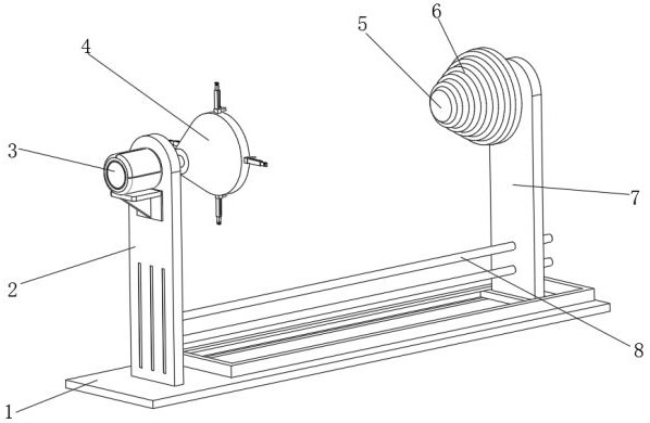
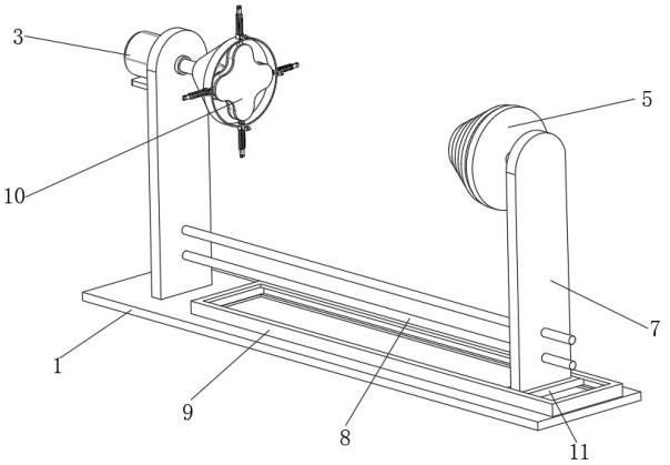
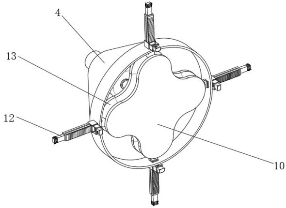
[0033] A high-efficiency and safe overturning device for steel structure processing, such as Figure 1-6As shown, it includes a base 1, the top of the base 1 is fixed with a first mounting frame 2 by bolts, the outer wall of one side of the first mounting frame 2 is fixed with a turning motor 3 by bolts, and the output end of the turning motor 3 is rotatably connected with a positioning cover 4 The center position of the inner wall on one side of the positioning cover 4 is fixed with a support motor 14 by bolts, and the output end of the support motor 14 is rotatably connected with a turret 10, and the turret 10 is a cross-shaped structure with a smooth transition on the outside. The outer wall of the turret 10 is provided with a chute 13, the outer wall of the positioning cover 4 is integrally provided with a guide frame 17, and the inner wall of the guide frame 17 is slidably connected with a support part 12, and one end of the support part 12 is integrally provided with a sl...
Embodiment 2
[0041] A high-efficiency and safe overturning device for steel structure processing, such as figure 1 , figure 2 As shown, in order to support the other end of the tubular and cylindrical steel structure; this embodiment makes the following improvements on the basis of embodiment 1: the outer wall of the top of the base 1 is fixed with a slide rail 9 by screws, and the inside of the slide rail 9 A slider 11 is slidably connected, and the top of the slider 11 is fixed with a second mounting frame 7 by bolts, and the inner wall of the second mounting frame 7 is connected with a support boss 5 through a shaft rotation, and the support boss 5 is a circular truncated structure. The diameter of the support boss 5 gradually decreases towards the direction close to the first mounting frame 2, and the position of the support boss 5 is adapted to the turret 10; on the inner wall of the other end of the tubular and cylindrical steel structure, and move in the slide rail 9 through the s...
PUM
 Abstract
Description
Claims
Application Information
 - R&D
- Intellectual Property
- Life Sciences
- Materials
- Tech Scout
- Unparalleled Data Quality
- Higher Quality Content
- 60% Fewer Hallucinations
Browse by: Latest US Patents, China's latest patents, Technical Efficacy Thesaurus, Application Domain, Technology Topic, Popular Technical Reports.
© 2025 PatSnap. All rights reserved.Legal|Privacy policy|Modern Slavery Act Transparency Statement|Sitemap|About US| Contact US: help@patsnap.com