Gas injection device of semiconductor heat treatment equipment and semiconductor heat treatment equipment

A technology of heat treatment equipment and gas injection, which is applied in semiconductor/solid-state device manufacturing, electrical components, gaseous chemical plating, etc., can solve the problems of inability to guarantee the uniformity of gas distribution, poor process results, and uneven gas volume, etc., to achieve guaranteed Consistency of process results, guarantee of thickness uniformity and process result consistency, effect of guarantee of thickness uniformity

Pending Publication Date: 2021-12-07
BEIJING NAURA MICROELECTRONICS EQUIP CO LTD
View PDF6 Cites 1 Cited by
  • Summary
  • Abstract
  • Description
  • Claims
  • Application Information

AI Technical Summary

Problems solved by technology

[0003] In the existing vertical heat treatment equipment, a gas injection device adopts an inverted U-shaped injection pipe, and a plurality of first air holes are distributed on the two pipe sections on both sides of the bend on the injection pipe, for The process gas is sprayed into the process chamber, wherein the first air holes on the two pipe sections are vertically interlaced to improve the uniformity of the gas output in the vertical direction, but the occupation of the above-mentioned U-shaped injection pipe The space is large, and it may not be able to be arranged in a processing container of a predetermined size, and the above-mentioned U-shaped spray tube is relatively close to the crystal boat, resulting in insufficient space for the gas sprayed from the first air hole on the two tube sections to mix evenly. As a result, the uniformity of gas distribution cannot be guaranteed, which may lead to uneven gas volumes obtained by different wafers, thereby adversely affecting process results

Method used


Image

  • Gas injection device of semiconductor heat treatment equipment and semiconductor heat treatment equipment
  • Gas injection device of semiconductor heat treatment equipment and semiconductor heat treatment equipment
  • Gas injection device of semiconductor heat treatment equipment and semiconductor heat treatment equipment

Examples


no. 1 example

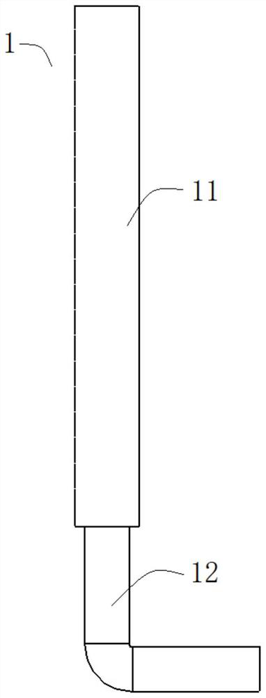
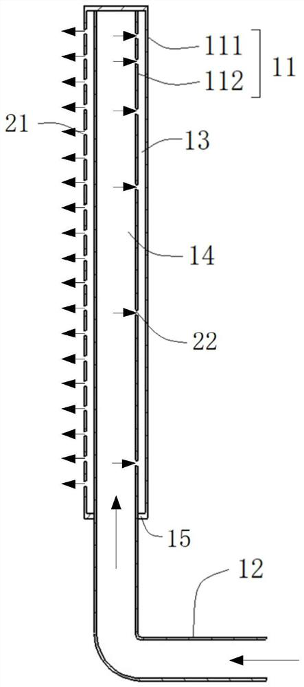
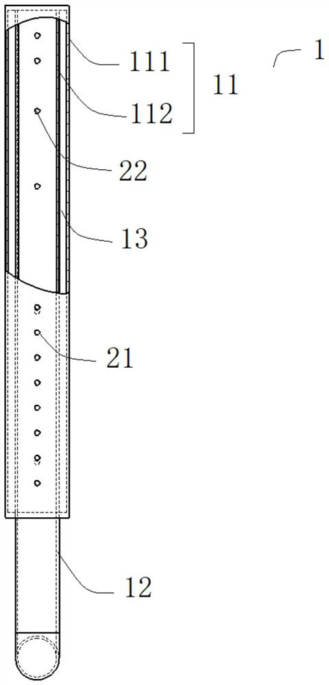
[0034] see figure 1 , the gas injection device provided in this embodiment is applied to semiconductor heat treatment equipment, especially vertical heat treatment equipment, the gas injection device includes an inlet pipe 1 for delivering process gas to the process chamber of the semiconductor heat treatment equipment, the The inlet pipe 1 comprises a first pipe section 11 and a second pipe section 12, wherein the first pipe section 11 is vertically arranged in the process chamber, and the upper end of the first pipe section 11 is closed, and the lower end of the first pipe section 11 is connected to the second pipe section 12 is connected to the upper end, and the lower end of the second pipe section 12 is connected to a gas source (not shown in the figure) for supplying process gas. Optionally, the lower end of the second pipe section 12 runs through the chamber wall of the process chamber, extends to the outside of the process chamber, and is connected to an external gas s...

no. 2 example

[0054] Please also refer to Figure 4 and Figure 5 , the gas injection device provided by this embodiment, compared with the above-mentioned first embodiment, also includes an air inlet pipe 3, and the air inlet pipe 3 includes a first pipe section 31 and a second pipe section 32, wherein the first pipe section 31 is vertically arranged In the process chamber, and the upper end of the first pipe section 31 is closed, the lower end of the first pipe section 31 is connected with the upper end of the second pipe section 32, and the lower end of the second pipe section 32 is connected with the gas source for providing process gas (in the figure not shown) connection.

[0055] Moreover, the first pipe section 31 adopts a double pipe wall structure, that is, the first pipe section 31 includes a first pipe wall 311 and a second pipe wall 312 nested in the first pipe wall 311, and the inner wall of the first pipe wall 311 A buffer space 33 is formed between the outer wall of the se...

no. 3 example

[0061] see Figure 6 , the gas injection device provided in this embodiment, compared with the above-mentioned first embodiment, also includes an air inlet pipe 5, and the air inlet pipe 5 includes a first pipe section 51 and a second pipe section 52, wherein the first pipe section 51 is vertically arranged In the process chamber, and the upper end of the first pipe section 51 is closed, the lower end of the first pipe section 51 is connected with the upper end of the second pipe section 52, and the lower end of the second pipe section 52 is connected with the gas source for providing process gas (in the figure not shown) connection.

[0062] Moreover, the first pipe section 51 adopts a double pipe wall structure, that is, the first pipe section 51 includes a first pipe wall 511 and a second pipe wall 512 nested in the first pipe wall 511, and the inner wall of the first pipe wall 511 A buffer space 53 is formed between the outer wall of the second pipe wall 512 , and the inn...


PUM


Abstract

The invention provides a gas injection device of semiconductor heat treatment equipment and the semiconductor heat treatment equipment. The device comprises a gas inlet pipe, wherein a first pipe section comprises a first pipe wall and a second pipe wall nested in the first pipe wall, and a buffer space is formed between the inner wall of the first pipe wall and the outer wall of the second pipe wall; a plurality of first gas holes are uniformly distributed in the first pipe wall in the vertical direction, and the first gas holes are communicated with the buffer space and a process chamber respectively; a plurality of second gas holes are formed in the second pipe wall, and the second gas holes are communicated with the interior of the second pipe wall and the buffer space respectively; and the change rule of the inner diameter of the second pipe wall in the vertical direction and/or the arrangement rule of the plurality of second gas holes meet the requirement that the gas output of process gas flowing into the buffer space through the plurality of second gas holes at different positions in the vertical direction is the same. According to the technical scheme, different wafers can obtain uniform gas amount, and then the thickness uniformity of wafer film forming and the consistency of process results can be guaranteed.

Description

technical field [0001] The invention relates to the field of semiconductor manufacturing, in particular to a gas injection device for semiconductor heat treatment equipment and semiconductor heat treatment equipment. Background technique [0002] Semiconductor heat treatment equipment, such as vertical heat treatment equipment, is the key equipment for film formation on the surface of semiconductor wafers. Its performance indicators such as process stability, uniformity, and reliability directly affect the electrical indicators and yield of chips. Especially when the vertical heat treatment equipment is applied to the film deposition process, in order to ensure uniform film thickness distribution between the wafers, the process gas should be supplied to the position of each wafer as evenly as possible. [0003] In the existing vertical heat treatment equipment, a gas injection device adopts an inverted U-shaped injection pipe, and a plurality of first air holes are distribut...

Claims


Application Information

Patent Timeline
Patent Type & Authority Applications(China)
IPC IPC(8): C23C16/455H01L21/67
CPCC23C16/45578H01L21/67098
Inventor 兰立广
Owner BEIJING NAURA MICROELECTRONICS EQUIP CO LTD
Why Eureka
Try Eureka