Lifting type tail yarn retaining device and control method

A tail-reserving, lift-type technology, applied in spinning machines, continuous winding spinning machines, textiles and papermaking, etc., can solve the problems of long manual operation time, not suitable for large-scale automated workshops, etc., and reduce the operation time. The effect of difficulty, ease of implementation, and simple control method

Pending Publication Date: 2021-12-07
YICHANG JINGWEI TEXTILE MACHINERY +1
View PDF9 Cites 0 Cited by
  • Summary
  • Abstract
  • Description
  • Claims
  • Application Information

AI Technical Summary

Problems solved by technology

In this method, the size of the thread sleeve is affected by the amount of tail yarn left, and there are space limitations in the design, and only a fixed length of tail yarn can be collected
CN 204023045 U has recorded a kind of two-for-one twister equ

Method used


Image

  • Lifting type tail yarn retaining device and control method
  • Lifting type tail yarn retaining device and control method
  • Lifting type tail yarn retaining device and control method

Examples


Embodiment 1

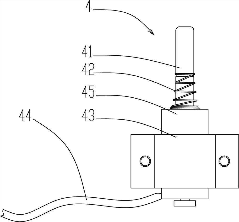
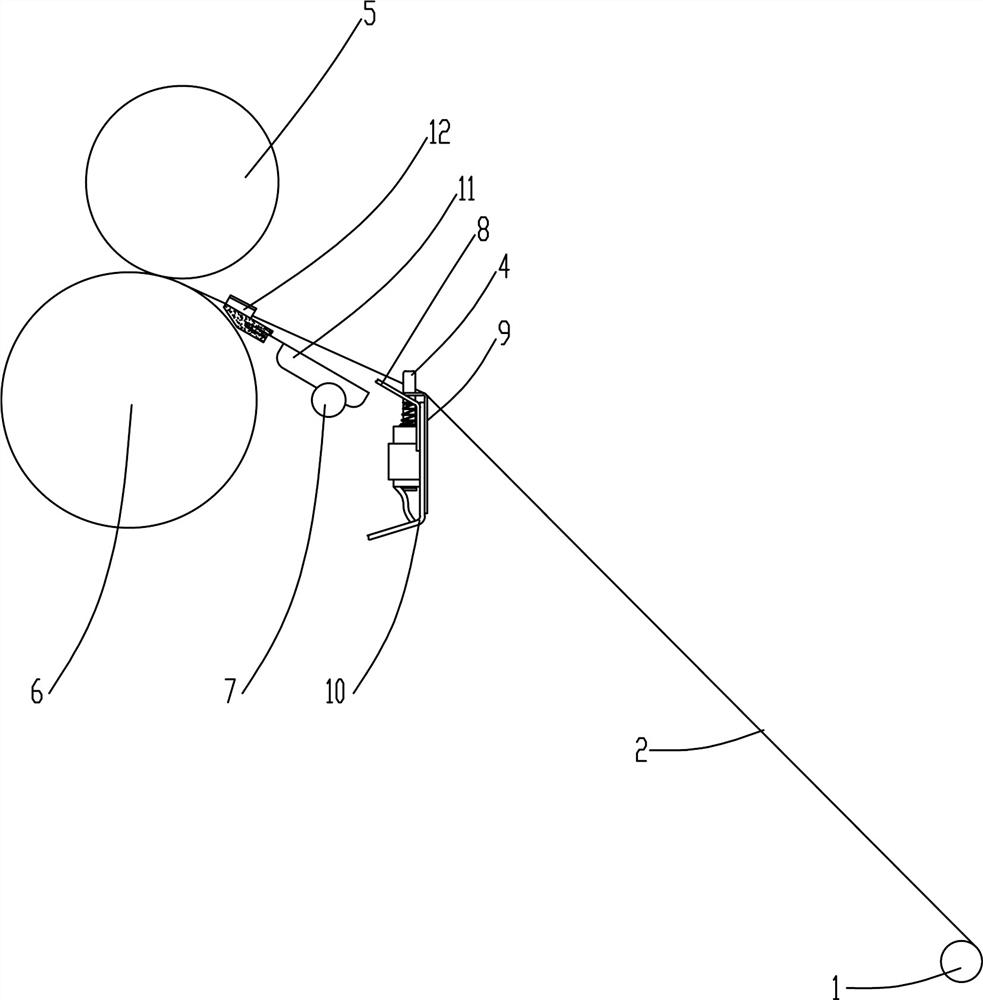
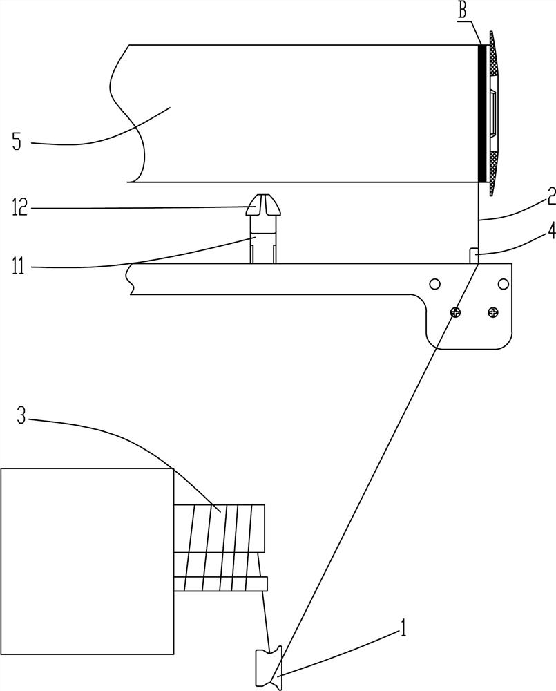
[0030] Such as Figure 2~4 Among them, a lift-type tailing yarn device includes a reel driving roller 6 and a reciprocating yarn guide device, and a tailing yarn device 4 is provided on the upstream side of the reciprocating yarn guide device near the tailing yarn section B at the end of the yarn drum 5 , the tail yarn device 4 is provided with a liftable lift bar 41, and the lift bar 41 is higher than the common tangent between the yarn guide plate 9 and the reel drive roller 6 when it is raised, so as to block the yarn 2 and make the yarn The line cannot move laterally, and the lift bar 41 is lower than the common tangent between the yarn guide plate 9 and the drum drive roller 6 when lowered, so as to release the yarn 2 . With this structure, it is realized to use the tail yarn keeping device 4 to block the yarn 2 after starting to carry out the tail yarn keeping operation, and to release the yarn 2 after completion.

[0031] The preferred solution is as figure 1 Among th...

Embodiment 2

[0040] A control method using the above-mentioned lifting type tail yarn device, comprising the following steps:

[0041] S1, the overfeeding parameter of yarn 2 is set, and the time parameter of leaving tail yarn is set by calculation, that is, the time for lifting and lowering bar 41 to block yarn 2; the time of leaving tail yarn in this example is set to 7s, this The time has determined how much the yarn 2 that stays tail yarn segment B is wound. It is related to the number of winding turns of the yarn 2 on the overfeeding device 3, the overfeeding ratio of the yarn 2, and the winding speed of the mandrel drive roller 6.

[0042] S2, hang the yarn 2 on the side of the lift bar 41 close to the end of the yarn reel 5;

[0043] S3, wind the tail yarn to the end of the yarn reel 5, and press the start button of the overfeeding device 3;

[0044] S4, the yarn 2 is winding the tail yarn, until the end of the set tail yarn time, the lift lever 41 descends to let the horizontal p...


PUM


Abstract

The invention provides a lifting type tail yarn retaining device. The lifting type tail yarn retaining device comprises a winding drum driving roller and a reciprocating yarn guide device; the tail yarn retaining device is arranged on the portion, close to the tail yarn retaining section of the end of a yarn winding drum, of the upstream part of the reciprocating yarn guide device; the tail yarn retaining device is provided with a lifting stop lever capable of ascending and descending; the lifting stop lever is higher than a common tangent line between a yarn guide plate and the winding drum driving roller when ascending, so that yarn is blocked from moving transversely; and the lifting stop lever is lower than the common tangent line between the yarn guide plate and the winding drum driving roller when descending, so that the yarn can be released. During use, time parameters of tail yarn remaining are set through calculation, and the lifting stop lever descends after the time of tail yarn remaining is over, so that the transverse position of the yarn is avoided; and the operation of automatically adjusting the tail yarn retaining length of the yarn is achieved. According to the lifting type tail yarn retaining device and the control method, automatic tail yarn retaining operation can be conveniently achieved, and the tail yarn retaining length can be freely set according to yarn varieties and customer requirements by setting the lifting time.

Description

technical field [0001] The invention relates to the field of twisting machines, in particular to a lift-type tail yarn retaining device and a control method. Background technique [0002] Tailing yarn refers to the operation of winding the untwisted waste silk directly on the end of the yarn drum when the yarn is wound on the yarn drum, so that subsequent users can distinguish where to start It is a qualified twisted yarn to ensure the quality of the final product. Chinese patent document 201922199294.6 describes an automatic yarn tailing device, which is to realize the function of automatic yarn tailing by locking the yarn in the thread groove and bringing the yarn from the bottom to the top by the helical movement of the threaded sleeve. In this method, the size of the threaded sleeve is affected by the amount of tail yarn left, and there is a space limitation in the design, and only a fixed length of tail yarn can be collected. CN 204023045 U has recorded a kind of two-...

Claims


Application Information

Patent Timeline
IPC IPC(8): D01H1/38D01H13/04
CPCD01H1/38D01H13/04
Inventor 张焕军杨华年张明聂俭张丕华王军
Owner YICHANG JINGWEI TEXTILE MACHINERY
Why Eureka
Try Eureka