Eccentric vibration type hydraulic pulse generating device

A technology of hydraulic pulse and generating device, which is applied to the driving device for drilling in the borehole, vibration drilling, drilling tools, etc., can solve the problems of high cost and inapplicability to special operations, and achieve low cost, improve drilling effect, and structure simple effect

Active Publication Date: 2021-12-07
SINOPEC SSC +2
View PDF7 Cites 0 Cited by
  • Summary
  • Abstract
  • Description
  • Claims
  • Application Information

AI Technical Summary

Problems solved by technology

[0007] The purpose of the present invention is to solve the problems existing in the prior art, to provide an eccentric vibration type hydraulic pulse generating device, which is used to s

Method used


Image

  • Eccentric vibration type hydraulic pulse generating device
  • Eccentric vibration type hydraulic pulse generating device

Examples


Embodiment 1

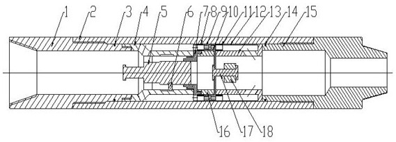
[0029] An eccentric vibration type hydraulic pulse generating device is composed of three parts: an outer cylinder, an inner cylinder and a pulse vibration device, wherein:

[0030] The outer cylinder is mainly composed of an upper joint 1, an outer cylinder body 2, and a lower joint 15 connected in sequence;

[0031] The inner cylinder includes an upper shunt joint 4, an inner cylinder sealing plug 5, a locking block 6, an upper cylinder body 7, a lower cylinder body 13 and a rotor fixing ring 16; wherein, the upper shunt joint 4 is a hollow cylinder with a thick top and a thin bottom. The upper end of the upper shunt joint 4 is connected to the upper joint 1, and the lower end of the upper shunt joint 4 is connected to the upper cylinder 7; the upper cylinder 7 is a hollow cylindrical structure, and the lower end is connected to the rotor The fixed ring 16 is connected, and the outer periphery is provided with a fixed limit block; the lower cylinder 13 is a hollow cylindrica...

Embodiment 2

[0034] On the basis of embodiment 1 further include:

[0035] The turbine stator 9 and the turbine rotor 10 are defined by the upper bearing 8 above the turbine stator 9 and the lower bearing 11 below the turbine rotor 10 on the periphery of a fixed ring 16 .

[0036] A compression ring 12 is arranged between the lower part of the lower bearing 11 and the thick diameter of the lower part of the lower cylindrical body 13 .

[0037] The belonging pressing ring 12 is a thin-walled ring.

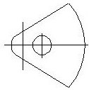
[0038] The turbine rotor 10 and the turbine stator 9 have a single-stage turbine structure, and the relative flow areas of the turbine stator 9 and the turbine rotor 10 have periodic changes.

[0039] The upper part of the upper cylinder 7 is an inner convex ring structure, which is inserted into the upper shunt joint 4; the upper part of the inner cylinder sealing plug 5 is provided with a fishing head, and the lower part forms a sealed plug connection with the inner convex ring structure of t...

Embodiment 3

[0042] see figure 1 , 2 , an eccentric vibration type hydraulic pulse generating device consists of three parts: an outer cylinder, an inner cylinder and a pulse vibration device. The outer cylinder includes upper joint 1, outer cylinder body 2, sealing ring 3, and lower joint 15; the inner cylinder includes upper shunt joint 4, inner cylinder sealing plug 5, locking block 6, upper cylinder body 7, upper bearing 8, and lower bearing 9. Compression ring 12, lower cylinder 13, sealing ring 14, rotor fixing ring 16; the pulse vibration device includes turbine stator 9, turbine rotor 10, eccentric shaft 17 and eccentric wheel 18. See figure 1 .

[0043]Among them: the upper joint 1 and the outer cylinder 2 are connected by the upper sealing ring 3 and the thread, the outer cylinder 2 and the lower joint 15 are connected by the lower sealing ring 14, and the upper shunt joint 4 and the inner cylinder sealing plug are arranged inside the outer cylinder 2 5. Locking block 6, uppe...


PUM


Abstract

The invention discloses an eccentric vibration type hydraulic pulse generating device. The device comprises an outer cylinder, an inner cylinder and a pulse vibration device. The outer cylinder comprises an upper joint, an outer cylinder body, a sealing ring and a lower joint; the inner cylinder comprises an upper shunting joint, an inner cylinder sealing plug, a locking block, an upper cylinder body, an upper bearing, a lower bearing, a pressing ring, a lower cylinder body, a sealing ring and a rotor fixing ring; and an eccentric rotating device comprises a turbine stator, a turbine rotor, an eccentric wheel shaft and an eccentric wheel. Drilling fluid passes through a turbine, the turbine is driven to rotate, periodic hydraulic pulses are generated, the turbine drives an eccentric wheel to rotate, and periodic vibration is generated, so that the drilling effect is improved; and special operation can be implemented by removing the inner cylinder sealing plug. The device is simple in structure, low in cost, stable, reliable and high in use flexibility.

Description

technical field [0001] The invention relates to the field of downhole drilling tools, in particular to an eccentric vibration hydraulic pulse generating device used in oil and gas drilling and workover operations. Background technique [0002] During the field drilling process of oil and natural gas exploration and development, downhole friction has become the main difficulty that actually limits the increase in the construction length of the horizontal drilling section. In field application, in order to overcome this difficulty, there are already hydraulic pulse axial vibration drag reduction tools, which can reduce the downhole friction by vibrating the drilling tool upwards to change the static friction between the drilling tool and the well wall into dynamic friction. [0003] For example, CN201386507Y discloses "A Rotary Blocking Type Hydraulic Pulse Drilling Tool", which includes a pulse sub casing, a compression nut, a turbine stator, a transmission shaft assembly, a ...

Claims


Application Information

Patent Timeline
IPC IPC(8): E21B4/16E21B7/24E21B12/00
CPCE21B4/16E21B7/24E21B12/00
Inventor 张锐张俊杰张辉李春光宁仁磊王彬赵传伟房泽永
Owner SINOPEC SSC
Why Eureka
Try Eureka