Limiting jig and limiting press-fit device

A limit and fixture technology, applied in the direction of material gluing, connecting components, electrical components, etc., can solve the problems of high mold cost and high demand for dimensional accuracy of workpiece alignment, to improve product quality, reduce dimensional accuracy requirements, The effect of reducing production costs

Active Publication Date: 2021-12-07
HORNG TERNG AUTOMATION
View PDF16 Cites 0 Cited by
  • Summary
  • Abstract
  • Description
  • Claims
  • Application Information

AI Technical Summary

Problems solved by technology

[0004] Wherein, a limit mold is set between the upper mold and the lower mold of the pressing fixture, and a workpiece alignment mold is formed on the limit mold. The side wall of the workpiece alignment port is formed with a guide slope that is inclined from the inside to the outside. The design of the guide slope inclined from the inside to the outside, so that the guide slope can push the heat sink during the pressing action, so that the heat sink and the substrate are automatically aligned. However, by using the workpiece When the alignment port provides the alignment function, the workpiece alignment port must match the shape design of the semiconductor element, and the dimensional accuracy of the workpiece alignment port is required to be high, resulting in higher mold manufacturing costs

Method used


Image

  • Limiting jig and limiting press-fit device
  • Limiting jig and limiting press-fit device
  • Limiting jig and limiting press-fit device

Examples


Embodiment Construction

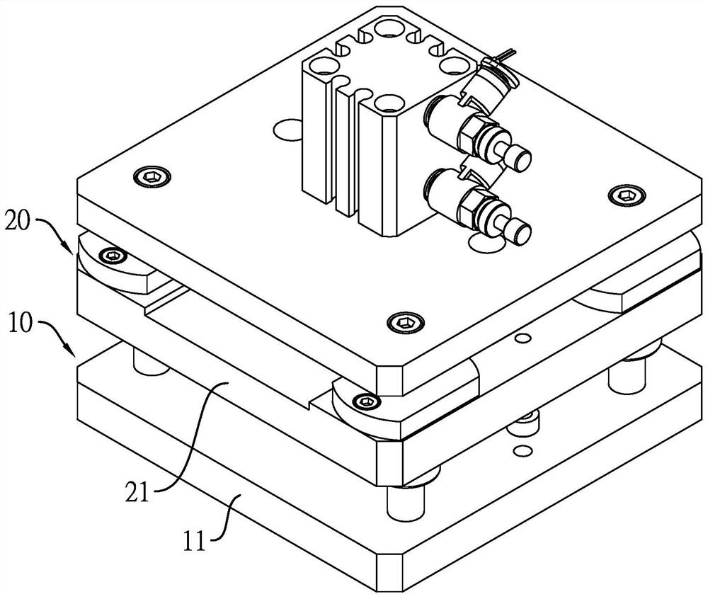
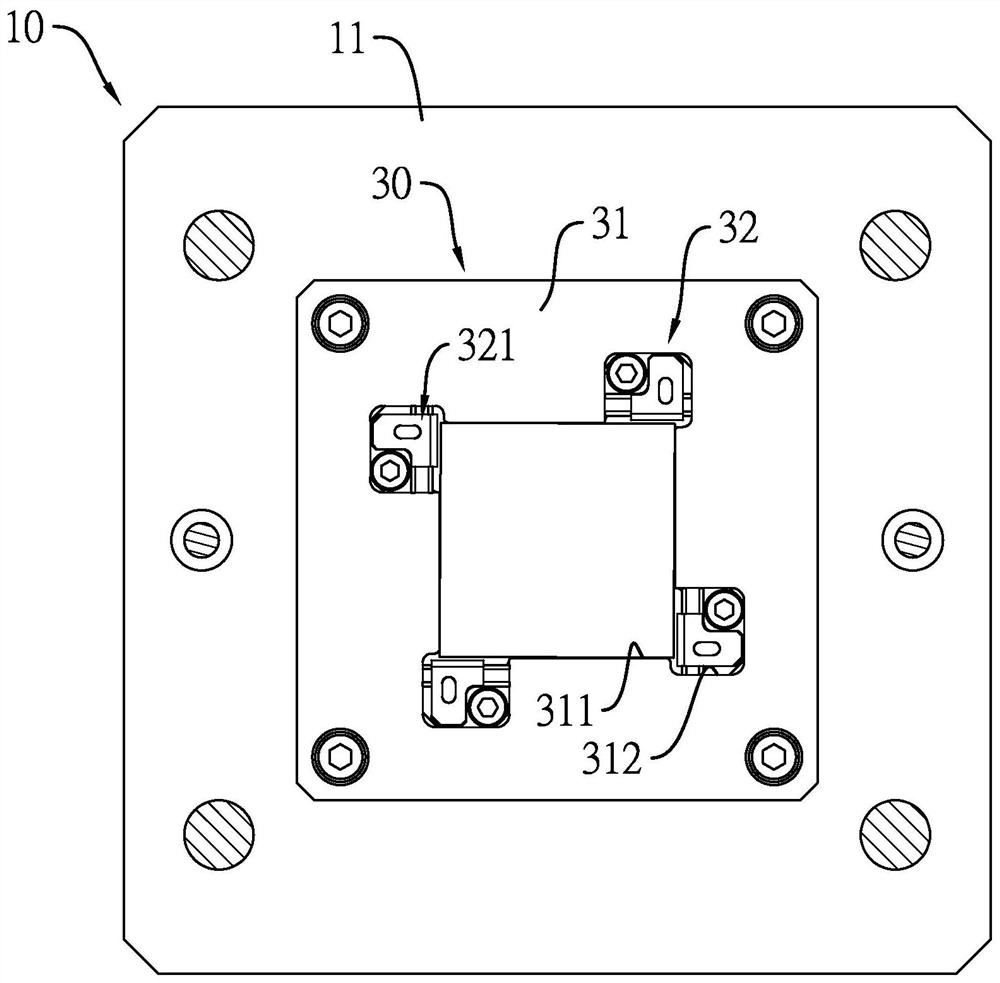
[0029] see Figure 1 to Figure 4 , is a preferred embodiment of the position-limiting jig of the present invention, which includes a lower mold 10 , an upper mold 20 and a position-limiting mechanism 30 .

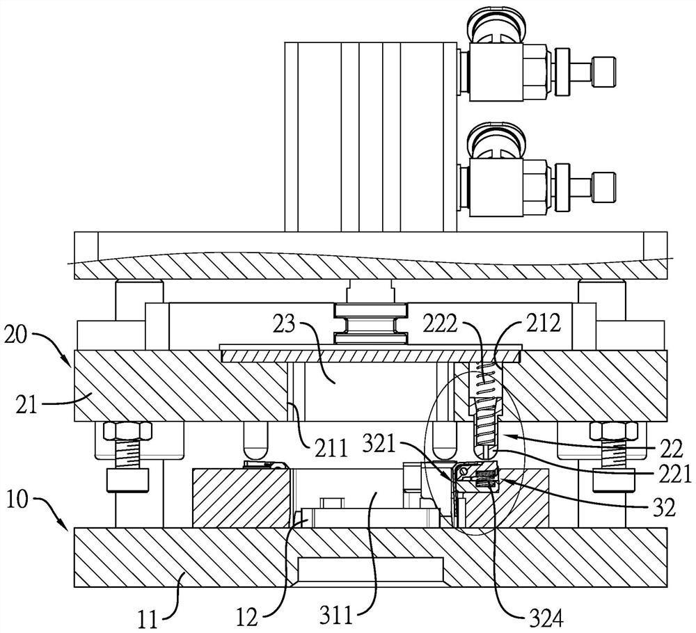
[0030] Such as Figure 1 to Figure 3 As shown, the upper mold 20 is installed above the lower mold 10, the upper mold 20 has at least one pressing component, and the pressing component includes a plurality of pressing structures 22, and the plurality of pressing structures 22 can stretch It is arranged at the bottom of the upper mold 20.

[0031] Wherein, the upper mold 20 includes an upper template 21, the upper template 21 forms a plurality of assembly holes 212, the pressing component is arranged on the upper template 21, each pressing structure 22 of the pressing component It includes a push post 221 and a push post reset part 222, the push posts 221 are respectively arranged in the plurality of assembly holes 212, and the push post 221 protrudes from the correspondin...


PUM


Abstract

The invention relates to a limiting jig and a limiting press-fit device. The limiting press-fit device comprises the limiting jig and a pressure supply mechanism connected with the limiting jig, and the limiting jig comprises an upper die, a lower die and a limiting mechanism, wherein the upper die and the lower die are opposite up and down and can move up and down, and the limiting mechanism is arranged between the upper die and the lower die. The limiting jig is mainly provided with a limiting assembly at a workpiece alignment opening of a limiting module, and the upper die is provided with corresponding pressing and abutting assemblies at the positions corresponding to limiting assemblies. Therefore, the limiting jig and the limiting press-fit device can mainly utilize limiting structures of the limiting mechanism to be matched with pressing and abutting structures of the upper die, and thus in the press-fit operation process, the upper part and the lower part of a workpiece can be respectively pushed and positioned through pushing parts of the limiting structures, so that not only can the device be suitable for the press-fit operation of workpieces with various sizes, but also the size precision requirement of the workpiece alignment opening can be reduced, and the production cost of the dies can be further reduced.

Description

technical field [0001] The invention relates to a position-limiting jig and a position-limiting pressing device, in particular to a position-limiting jig and a position-limiting pressing device for positioning substrates and cooling fins such as semiconductor elements and providing pressing operations. Background technique [0002] With the advancement of science and technology, people's requirements for information processing speed have increased, and the existing semiconductor components are gradually developing towards high frequency, and high-frequency semiconductor components are prone to high temperatures during operation. Therefore, in order to avoid damage to semiconductor components due to high temperatures Or the problem of performance degradation. In addition to the cooling effect provided by the external heat dissipation structure, the semiconductor element will press a heat sink with improved heat dissipation function on the substrate with the semiconductor chip ...

Claims


Application Information

Patent Timeline
Patent Type & Authority Applications(China)
IPC IPC(8): F16B11/00H01L21/67
CPCF16B11/002F16B11/006H01L21/67092H01L21/67121
Inventor 王裕贤林智远
Owner HORNG TERNG AUTOMATION
Why Eureka
Try Eureka