Building inclination warning equipment capable of automatically monitoring sag for building monitoring
An architectural and automatic technology, applied in the direction of measuring inclination, measuring device, mapping and navigation, etc., can solve the problems of affecting the efficiency of detection, the observation effect is not obvious, and the efficiency is low.
- Summary
- Abstract
- Description
- Claims
- Application Information
AI Technical Summary
Problems solved by technology
Method used
Image
Examples
Embodiment 1
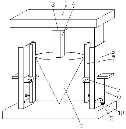
[0033] see Figure 1-8 According to an embodiment of the present invention, a building tilt warning device for building monitoring that can automatically monitor the sag includes two horizontal plates 1, and the four corner edges between the horizontal plates 1 are fixed with telescopic Rod, the total number of the telescopic rods is four, two connecting plates 2 are provided between the horizontal plates 1, and a connecting seat 3 is fixed in the middle of the bottom end of the horizontal plate 1 above. The bottom end of the connecting seat 3 is movably equipped with a swing arm rod 4, the inside of the swing arm rod 4 is cavity-shaped, and the bottom end of the swing arm rod 4 is fixed with a monitoring top 5, and the middle part of the connecting plate 2 facing the side wall The lower position is symmetrically provided with a support 6, and the support 6 is hingedly connected with a contact plate 7 cooperating with the monitoring top 5, and one end of the contact plate 7 lo...
Embodiment 2
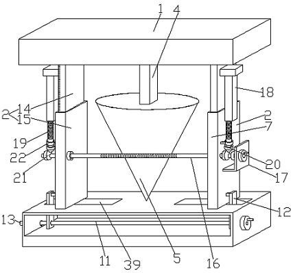
[0035] see figure 2 , the interior of the horizontal plate 1 located below is cavity-shaped, and the distance adjustment mechanism includes a screw rod 11 arranged inside the horizontal plate 1, and two moving plates are sleeved on the screw rod 11 with opposite threads 12. The moving plate 12 passes through the top of the horizontal plate 1, and the moving plate 12 and the corresponding connecting plate 2 are fixedly connected by connecting rods, and both ends of the screw rod 11 pass through the top of the horizontal plate 1. The horizontal plate 1 is described, and one end of the screw rod 11 is fixed with a turntable, and the other end of the screw rod 11 is covered with a bushing 13, and the bushing 13 is fixed on the outer wall of the horizontal plate 1, and the connecting plate 2 The top is T-shaped, and the bottom of the horizontal plate 1 above is provided with a T-shaped chute, the top of the connecting plate 2 is slidably arranged in the T-shaped chute, and the top...
Embodiment 3
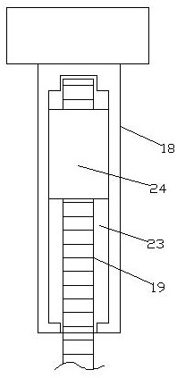
[0038] see Figure 2-4 , the connecting plates 2 are respectively an upper plate 14 and a lower plate 15, the interior of the lower plate 15 is cavity-shaped, and the upper plate 14 is inserted into the lower plate 15, and the lower plates 15 are penetrated There are round rods 16, one of which is provided with an L-shaped plate 17 on the outer wall of the lower plate 15, one end of the round rod 16 passes through the L-shaped plate 17, and the inner side of the L-shaped plate 17 and the other The inner side of the lower plate 15 is fixed with a secondary bushing, and one end of the upper plate 14 away from each other is fixed with a fixed block 2, and the bottom end of the fixed block 2 is fixed with a threaded long block 18, and the threaded long block 18 The internal thread is connected with a threaded rod 19, and the bottom end of the threaded rod 19 is fixed with a bevel gear 20, and the bevel gear 20 is meshed with a secondary bevel gear 21, and the secondary bevel gear ...
PUM
 Abstract
Description
Claims
Application Information
 - R&D
- Intellectual Property
- Life Sciences
- Materials
- Tech Scout
- Unparalleled Data Quality
- Higher Quality Content
- 60% Fewer Hallucinations
Browse by: Latest US Patents, China's latest patents, Technical Efficacy Thesaurus, Application Domain, Technology Topic, Popular Technical Reports.
© 2025 PatSnap. All rights reserved.Legal|Privacy policy|Modern Slavery Act Transparency Statement|Sitemap|About US| Contact US: help@patsnap.com


