

Optical lens and electronic equipment
An optical lens and lens technology, applied in the field of optical components, can solve the problems affecting the miniaturization of the lens, increase the cost, and reduce the performance of the lens, and achieve the effects of small distortion, large field of view, and low cost.
- Summary
- Abstract
- Description
- Claims
- Application Information
AI Technical Summary
Problems solved by technology
Method used
Image

Examples
Embodiment 1
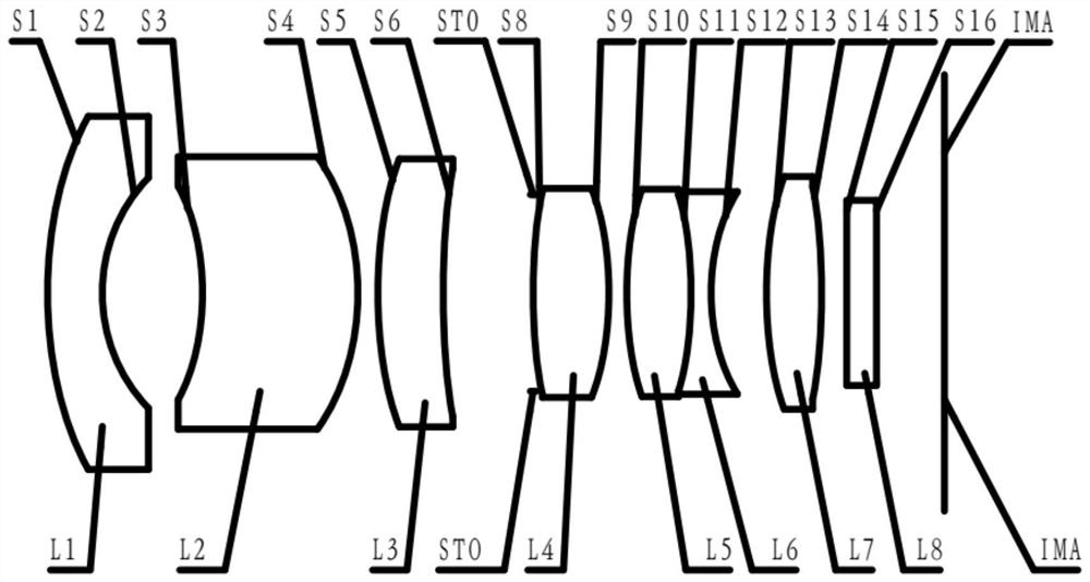
[0099] Refer to the following figure 1 An optical lens according to Embodiment 1 of the present application is described. figure 1 is a schematic diagram showing the structure of an optical lens according to Embodiment 1 of the present application.
[0100] Such as figure 1 As shown, the optical lens includes in sequence from the object side to the image side along the optical axis: the first lens L1, the second lens L2, the third lens L3, the diaphragm STO, the fourth lens L4, the fifth lens L5, and the sixth lens L6, the seventh lens L7.
[0101] The first lens L1 is a meniscus lens with negative refractive power, the object side S1 is convex, the image side S2 is concave, and both the object side S1 and the image side S2 of the first lens L1 are spherical.
[0102] The second lens L2 is a meniscus lens with negative refractive power, the object side S3 is concave, the image side S4 is convex, and both the object side S3 and the image side S4 of the second lens L2 are asp...
Embodiment 2
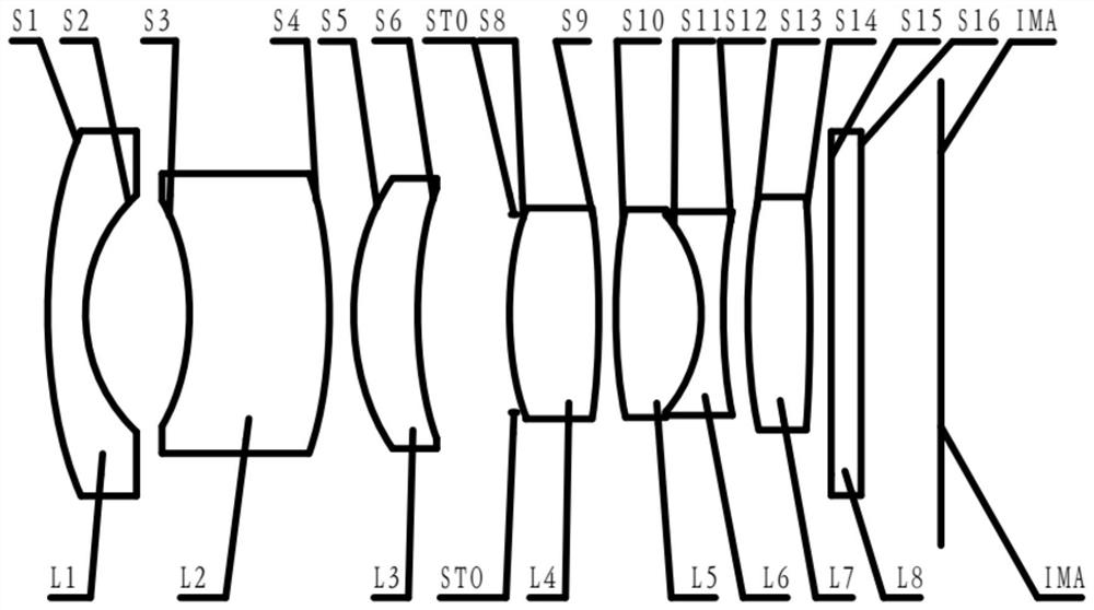
[0123] Refer to the following figure 2 An optical lens according to Embodiment 2 of the present application is described. figure 2 is a schematic diagram showing the structure of an optical lens according to Embodiment 2 of the present application.
[0124] Such as figure 2As shown, the optical lens includes in sequence from the object side to the image side along the optical axis: the first lens L1, the second lens L2, the third lens L3, the diaphragm STO, the fourth lens L4, the fifth lens L5, and the sixth lens L6, the seventh lens L7.
[0125] The first lens L1 is a meniscus lens with negative refractive power, the object side S1 is convex, the image side S2 is concave, and both the object side S1 and the image side S2 of the first lens L1 are spherical.
[0126] The second lens L2 is a meniscus lens with negative refractive power, the object side S3 is concave, the image side S4 is convex, and both the object side S3 and the image side S4 of the second lens L2 are a...
Embodiment 3
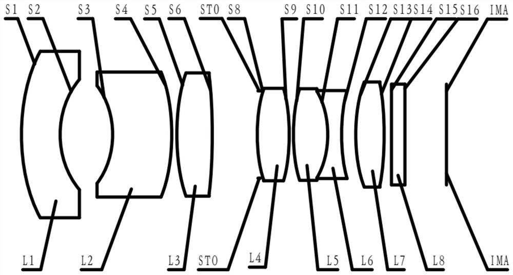
[0146] Refer to the following image 3 An optical lens according to Embodiment 3 of the present application will be described. image 3 is a schematic diagram showing the structure of an optical lens according to Embodiment 3 of the present application.
[0147] Such as image 3 As shown, the optical lens includes in sequence from the object side to the image side along the optical axis: the first lens L1, the second lens L2, the third lens L3, the diaphragm STO, the fourth lens L4, the fifth lens L5, and the sixth lens L6, the seventh lens L7.
[0148] The first lens L1 is a meniscus lens with negative refractive power, the object side S1 is convex, the image side S2 is concave, and both the object side S1 and the image side S2 of the first lens L1 are spherical.
[0149] The second lens L2 is a meniscus lens with positive refractive power, the object side S3 is concave, the image side S4 is convex, and both the object side S3 and the image side S4 of the second lens L2 ar...
PUM
 Abstract
Description
Claims
Application Information