Miniature heat dissipation system

A heat dissipation system and miniature technology, which can be used in decoration through conduction and heat transfer, cooling/ventilation/heating transformation, electrical equipment structural parts, etc. To solve the effect of easy to produce eccentric

Pending Publication Date: 2021-12-07
王士荣
View PDF0 Cites 0 Cited by
  • Summary
  • Abstract
  • Description
  • Claims
  • Application Information

AI Technical Summary

Problems solved by technology

Therefore, it is easy to cause excessive power consumption of the electronic device, causing the user to frequently charge the electronic device
[0005] Moreover, since the motor rotor of the existing fan is wound with coils, it is easy to cause the overall weight of the rotor to be uneven, which will cause the center of gravity of the rotor to shift, so that the rotor cannot be balanced when it rotates, causing the problem of eccentricity

Method used


Image

  • Miniature heat dissipation system
  • Miniature heat dissipation system
  • Miniature heat dissipation system

Examples


no. 1 example

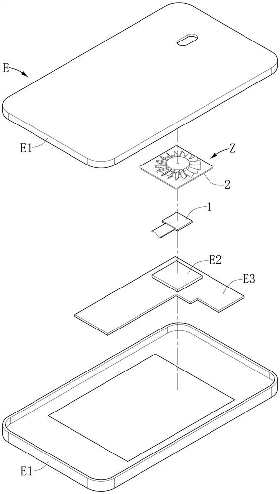
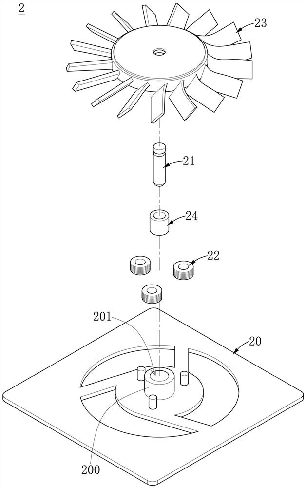
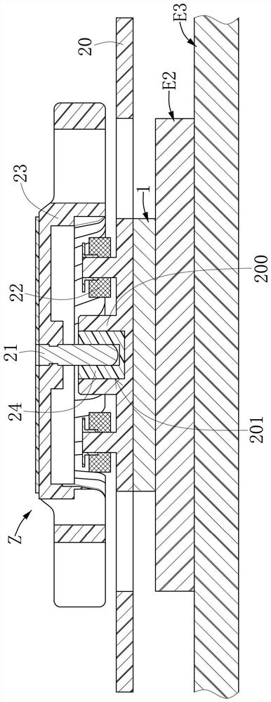
[0030] see Figure 1 to Figure 4 , are respectively a three-dimensional schematic diagram, a partial cross-sectional schematic diagram, an exploded schematic diagram of a heat dissipation module, and a functional block diagram of the micro cooling system according to the first embodiment of the present invention. As shown in the figure, the first embodiment of the present invention provides a miniature heat dissipation system Z, which is suitable for an intelligent communication device E. The intelligent communication device E includes a housing element E1 and a processing element E2 located in the housing element E1. The cooling system Z includes a sensing module 1 , a cooling module 2 and a control module 3 . The sensing module 1 is disposed on the processing element E2, and the sensing module 1 detects the temperature of the processing element E2 to generate at least one piece of temperature information. The heat dissipation module 2 includes a base plate unit 20 , a rotor...

no. 2 example

[0041] see Figure 5 and Figure 6 , are respectively the first structural schematic diagram and the second structural schematic diagram of the micro cooling system of the second embodiment of the present invention, and please refer to Figure 1 to Figure 4 . As shown in the figure, the operation mode of the same components of the miniature heat dissipation system of this embodiment is similar to that of the above-mentioned first embodiment, and will not be repeated here. It is worth noting that in this embodiment, the micro heat dissipation system Z further includes a heat conduction module 4 , and the heat conduction module 4 includes a heat absorption unit 40 , a conduit unit 41 and a heat release unit 42 . The heat absorption unit 40 is disposed on the processing element E2. One end of the duct unit 41 is connected to the heat absorption unit 40 . The heat release unit 42 is connected to the other end of the conduit unit 41 . Wherein, the heat absorption unit 40 absor...

no. 3 example

[0046] see Figure 7 , is the functional block diagram of the miniature cooling system of the third embodiment of the present invention, and please refer to it together Figure 1 to Figure 6 . As shown in the figure, the operation mode of the same components of the micro cooling system of this embodiment is similar to that of the micro cooling systems of the above-mentioned embodiments. It further includes a charging module 5, the charging module 5 includes a plurality of power generation units 50, the plurality of power generation units 50 are arranged on the other side of the substrate unit 20, and surround the rotor unit 21, and the plurality of power generation units 50 are electrically connected to the control module 3 and the intelligent The power supply element E4 of the type communication device E, the plurality of power generation units 50 generate electric energy according to the rotation of the rotor unit 21, and the plurality of power generation units 50 transmit ...


PUM


Abstract

The invention discloses a miniature heat dissipation system, which is suitable for an intelligent communication device and comprises a sensing module, a heat dissipation module and a control module. The sensing module is arranged on the processing element, and the sensing module detects the temperature of the processing element to generate temperature information. The heat dissipation module comprises a substrate unit, a rotor unit, a plurality of stator units and a fan blade unit. One surface of the substrate unit is connected to the sensing module. The rotor unit is arranged on the other surface of the substrate unit. The plurality of stator units are arranged on the other surface of the substrate unit, and the plurality of stator units surround the rotor unit. The fan blade unit is connected to the rotor unit. The control module is electrically connected with the sensing module and the heat dissipation module, and when the control module receives the temperature information and judges that the temperature information exceeds a temperature threshold value, the control module provides electric energy to the stator units so as to drive the fan blade unit to conduct heat dissipation operation on the processing element. Therefore, the miniature heat dissipation system provided by the invention can achieve an energy-saving effect.

Description

technical field [0001] The invention relates to a heat dissipation system, in particular to a miniature heat dissipation system applied in an intelligent communication device. Background technique [0002] With the rapid development of technology, the appearance of electronic devices such as notebook computers, tablet computers or smart phones are all designed to be light, thin, short and small, so as to reduce the space occupied by electronic devices and facilitate users to carry them. [0003] Generally, electronic devices will generate heat during operation. Therefore, some people have developed a fan inside the computer to discharge the hot air generated by the computer during operation through the fan, or use the fan to blow cold air to the heat source to assist in heat dissipation. , to ensure the overall cooling effect. However, in a general mobile phone, due to the limited space, it is difficult to install a general fan therein, and cannot provide convection heat di...

Claims


Application Information

Patent Timeline
Patent Type & Authority Applications(China)
IPC IPC(8): G06F1/20
CPCG06F1/203G06F1/206H05K7/20209Y02D10/00H05K7/2039H05K7/20172
Inventor 王士荣
Owner 王士荣
Why Eureka
Try Eureka