Braking method of high-rotating-speed handle, and controller

A high-speed, controller technology, used in motor control, AC motor control, AC motor acceleration/deceleration control, etc., can solve problems such as inability to brake quickly, and achieve the purpose of avoiding secondary damage, widely using value, and protecting safety. Effect

Pending Publication Date: 2021-12-07
嘲风医疗科技(无锡)有限公司
View PDF4 Cites 0 Cited by
  • Summary
  • Abstract
  • Description
  • Claims
  • Application Information

AI Technical Summary

Problems solved by technology

[0004] The technical problem to be solved by the present invention is to provide a braking method and controller of a high-speed handle to solve the problem in the prior art that the handle cannot be braked quickly after use

Method used


Image

  • Braking method of high-rotating-speed handle, and controller
  • Braking method of high-rotating-speed handle, and controller
  • Braking method of high-rotating-speed handle, and controller

Examples


Embodiment Construction

[0043] In order to further explain the technical means and effects of the present invention to achieve the intended purpose of the invention, the specific implementation of a high-speed handle braking method and controller according to the present invention will be described below in conjunction with the accompanying drawings and preferred embodiments. The method and its effect are described in detail below.

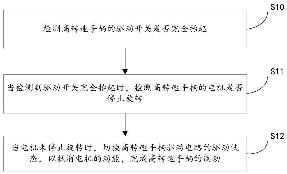
[0044] An embodiment of the present invention provides a braking method based on a high-speed handle, such as figure 1 shown, including:

[0045] Step S10, detecting whether the drive switch of the high-speed handle is fully lifted.

[0046] During the use of the high-speed handle, the opening, closing and speed regulation of the high-speed handle are usually controlled by a foot switch. When the foot switch is depressed, the high-speed handle is turned on; when the foot switch is fully lifted, the operation of the high-speed handle is turned off. Of course, the switc...


PUM


Abstract

The invention discloses a braking method of a high-rotating-speed handle, and a controller. The method comprises the steps that: whether a driving switch of the high-rotating-speed handle is completely lifted or not is detected; when it is detected that the driving switch is completely lifted, whether a motor of the high-rotating-speed handle stops rotating or not is detected; and when the motor does not stop rotating, the driving state of the high-rotating-speed handle driving circuit is switched to offset kinetic energy of the motor, and braking of the high-rotating-speed handle is completed. A short-circuit braking mode is adopted, so that the high-rotating-speed handle can be braked without adding mechanical parts and hardware circuits, the weight of the high-rotating-speed handle is reduced, and the circuit is simplified.

Description

technical field [0001] The invention relates to the technical field of motor control, in particular to a braking method and controller for a high-speed handle. Background technique [0002] In spine surgery, orthopedics and neurosurgery, it is necessary to plan and grind the diseased bone tissue and open the inner channel by turning the scalpel; therefore, it is necessary to drive the knife head to rotate and have certain flexibility Operability, so it is necessary to be equipped with a control host and a handle that transmits power to the cutter head. The control host drives and controls the cutter head by controlling the motor built in the power handle, so as to successfully complete the operation process. [0003] However, after the operation is completed, due to the high-speed rotation of the power handle, the handle cannot stop rotating immediately under the action of inertia after the power supply of the power handle is cut off in time, and it is very easy to cause sec...

Claims


Application Information

Patent Timeline
Patent Type & Authority Applications(China)
IPC IPC(8): H02P3/22H02P6/17H02P23/00H02P23/20H02P23/28H02P27/04H02P29/024H02P29/028H02P29/032A61B17/00
CPCH02P3/22H02P6/17H02P23/0004H02P23/20H02P23/28H02P27/04H02P29/027H02P29/028H02P29/032A61B17/00A61B2017/00199A61B2017/00017
Inventor 陈保明
Owner 嘲风医疗科技(无锡)有限公司
Why Eureka
Try Eureka