Camera module and assembling method

The technology of a camera module and assembly method, which is applied in the field of optics, can solve the problems that the resolution cannot be guaranteed, and the glue thickness of the camera module is different.

Pending Publication Date: 2021-12-07
ZHEJIANG SUNNY SMARTLEAD TECH CO LTD
View PDF0 Cites 1 Cited by
  • Summary
  • Abstract
  • Description
  • Claims
  • Application Information

AI Technical Summary

Problems solved by technology

[0006] The purpose of the present invention is to solve the above problems, provide a camera module and an assembly method, and solve the problem that the resolution cannot be guaranteed due to the inconsistent glue thickness of the same batch of camera modules

Method used


Image

  • Camera module and assembling method
  • Camera module and assembling method
  • Camera module and assembling method

Examples


Embodiment approach

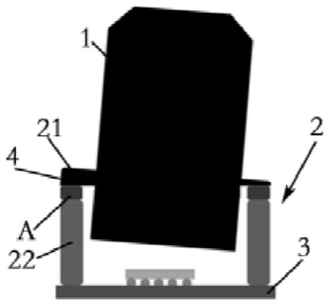
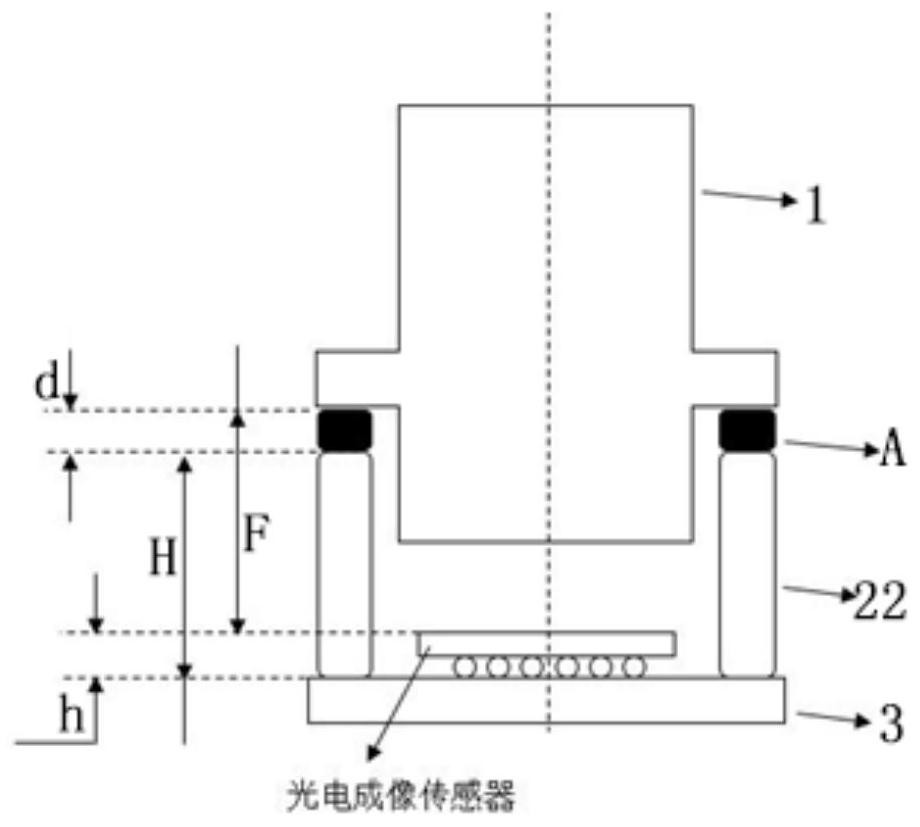
[0058] combine Figure 1-Figure 5 As shown, according to the first embodiment of the present invention, both the first connecting portion 21 and the second connecting portion 22 of the connecting piece 2 are separate components. In this embodiment, the first connecting portion 21 is a connecting flange, the first connecting portion 21 is fixedly connected to the lens 1 , and the second connecting portion 22 is a mirror base. Such as figure 2 As shown, in an ideal state, the base is assembled with the circuit board 3, and then the lens 1 is AA-assembled with the base and the circuit board 3. After finding the best imaging position of the lens, fill the glue (connecting glue layer) to the first The connection part 21 is fixedly connected to the second connection part 22 .

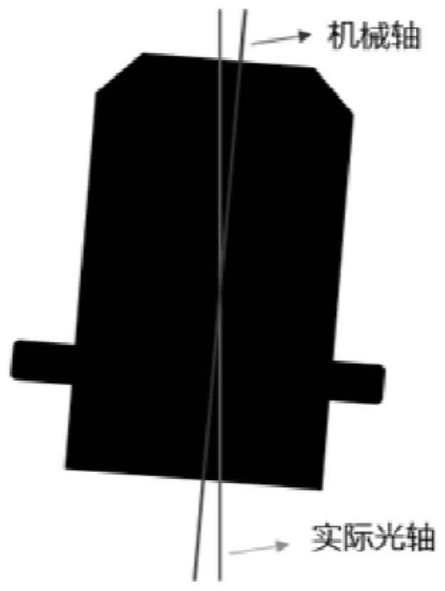
[0059] combine image 3 and Figure 4 As shown, however, in the actual assembly process of the camera module, there is a certain angle deviation between the mechanical axis of the lens 1 and the actual o...


PUM


Abstract

The invention relates to a camera module and an assembling method. The camera module comprises a lens, a connecting piece, a circuit board and a photoelectric imaging sensor arranged on the circuit board. Along the optical axis direction, the connecting piece comprises a first connecting part fixedly connected with the lens and a second connecting part connected with the circuit board. The side, facing the second connecting part, of the first connecting part is provided with a correction plane, or the side, close to the circuit board, of the second connecting part is provided with a correction plane. The correction plane is parallel to the imaging plane of the lens; and a connecting adhesive layer with a preset thickness is arranged between the correction plane and the second connecting part or between the correction plane and the circuit board. The camera module provided by the invention can ensure that the filled glue thickness (connecting glue layer) is consistent in the AA manufacturing process, particularly can ensure that the glue thickness of all camera modules is consistent and the glue shrinkage amount is consistent, and improves the consistency and qualified rate of products.

Description

technical field [0001] The invention belongs to the field of optical technology, in particular to a camera module and an assembly method. Background technique [0002] With the continuous development of photoelectric imaging sensors and image processing system platforms, the demand for image processing algorithms is getting higher and higher, making the resolution of cameras higher and higher, especially in non-consumer fields, including automotive and security cameras. Pixels have been gradually phased out. With the continuous upgrading of photoelectric imaging sensor pixels, the resolution of the lens in the camera is required to be higher and higher, but compared with the photoelectric imaging sensor, the resolution margin of the lens is getting smaller and smaller, that is, the focal depth range of the camera module is getting smaller and smaller. It requires higher precision when assembling the camera module. In addition, non-consumer camera modules are basically fixe...

Claims


Application Information

Patent Timeline
Patent Type & Authority Applications(China)
IPC IPC(8): H04N5/225
CPCH04N23/50H04N23/54H04N23/55H04N23/57G02B7/003G02B7/023G02B7/025H05K1/181H05K2201/10121G02B7/02H05K3/321G02B7/004
Inventor 张扣文刘召庆许银锋农开勋周迪长
Owner ZHEJIANG SUNNY SMARTLEAD TECH CO LTD
Why Eureka
Try Eureka