
Automatic screw machine capable of achieving convenient use and material conveying and working efficiently

A screw machine and automatic technology, which is applied in metal processing machinery parts, manufacturing tools, metal processing, etc., can solve the problems of inconvenient, not fast enough screwing, and the size of the roller can not be large, so as to reduce the trouble of use and facilitate on-site installation , the effect of improving efficiency

Pending Publication Date: 2021-12-10
深圳市扬哲科技有限公司
View PDF0 Cites 4 Cited by
  • Summary
  • Abstract
  • Description
  • Claims
  • Application Information

AI Technical Summary

Problems solved by technology

Either the screw feeder and arrangement machine equipped in the distance need air pipes to send the arranged screws to the bottom of the electric screwdriver. The screws cannot be fed to the bottom of the electric screwdriver quickly at close range, and the screwing speed is not fast enough.
Moreover, the traditional screw feeder is either a large spiral screw system, and the whole screw feeder is placed side by side on the side of the screw machine, or a slightly smaller roller feeder in recent years, because the roller It cannot be very large, and users need to add screws regularly, which is very inconvenient and has problems with material delivery and efficiency

Method used


Image

  • Automatic screw machine capable of achieving convenient use and material conveying and working efficiently
  • Automatic screw machine capable of achieving convenient use and material conveying and working efficiently
  • Automatic screw machine capable of achieving convenient use and material conveying and working efficiently

Examples


Embodiment Construction

[0029]The following will clearly and completely describe the technical solutions in the embodiments of the present invention with reference to the accompanying drawings in the embodiments of the present invention. Obviously, the described embodiments are only some, not all, embodiments of the present invention. Based on the embodiments of the present invention, all other embodiments obtained by persons of ordinary skill in the art without making creative efforts belong to the protection scope of the present invention.

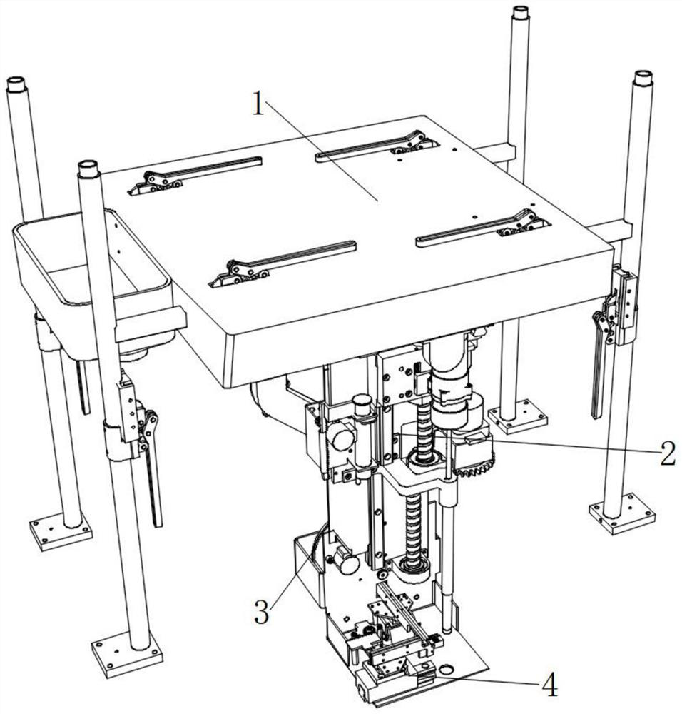
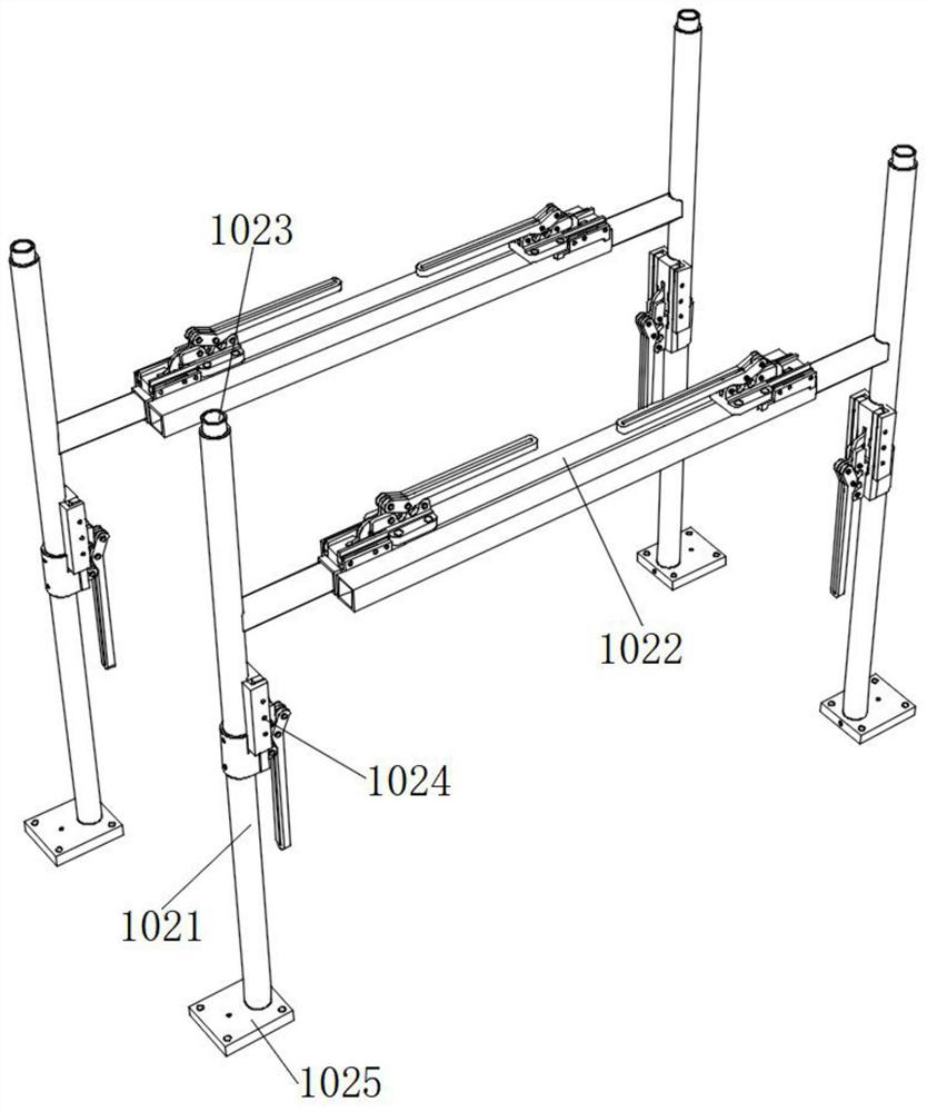
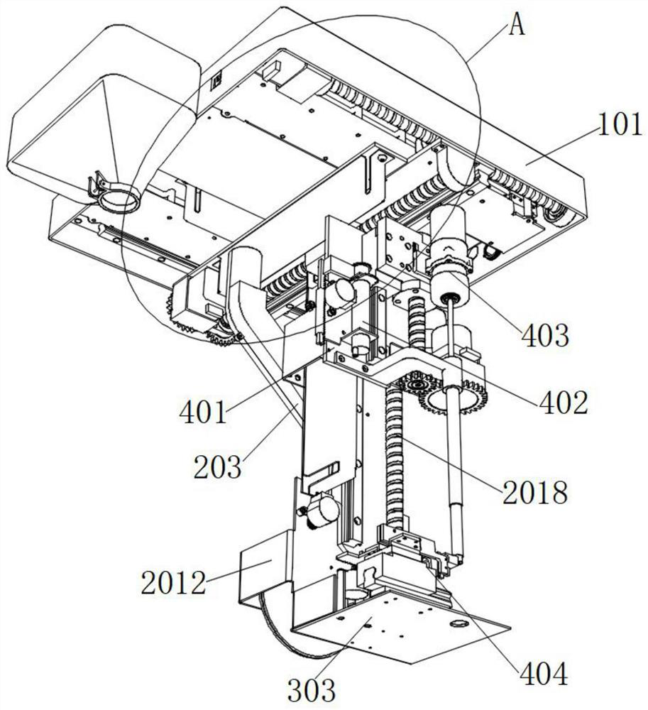
[0030] see Figure 1-11 As shown, an automatic screw machine that can realize convenient use and material feeding and work efficiently includes a frame body mechanism 1, an automatic feeding mechanism 2, an arrangement mechanism 3 and an automatic material pushing mechanism 4; among them, the frame body mechanism 1 Including a mounting frame 101, two adjustment devices 102 are provided on both sides of the mounting frame 101, and a hopper 103 is fixedly connect...


PUM


Abstract

The invention relates to the technical field of automatic screw machines, in particular to an automatic screw machine capable of achieving convenient use and material conveying and working efficiently. The automatic screw machine comprises a frame body mechanism, an automatic feeding mechanism, an arrangement mechanism and an automatic material pushing mechanism; the frame body mechanism comprises a mounting frame, the two sides of the mounting frame are each provided with two adjusting devices, and one side of the mounting frame is fixedly connected with a hopper; square pipes can limit the running track by themselves, and the operation that a corresponding rotation limiting mechanism is additionally arranged so as to reduce the probability that the mounting frame is unstable due to shaking during normal running is not needed; first circular pipes and second circular pipes which are designed to be cylindrical are adopted, and compared with other shapes, cylinders can rotate through bottom supporting blocks, and field mounting is convenient; and a needle cylinder is pushed to suck air to adsorb a screw head firmly below an electric screwdriver bit, and therefore a screw can be conveyed to the position above a screw hole to be drilled, and due to the fact that the automatic screw machine does not need to be connected with a compressed air path like a traditional screw machine, use trouble is reduced.

Description

technical field [0001] The invention relates to an automatic screw machine, in particular to an automatic screw machine capable of convenient use and material feeding and efficient work, and belongs to the technical field of automatic screw machines. Background technique [0002] The traditional automatic screw machine is fixedly installed in one place, and then the machine arm stretches and moves back and forth to screw the screw. Since the mounting frame cannot be stretched and adjusted, the predetermined space must be relatively large. The general automatic screw machine is long, wide and high. There is 1-2 meters, which is not conducive to product packaging, transportation and export overseas, and there is not enough space for installation and use according to local conditions. [0003] At the same time, the traditional automatic screw machine needs to be connected to the compressed air of the factory workshop because it needs gas to blow up the screw or absorb the screw...

Claims


Application Information

Patent Timeline
Patent Type & Authority Applications(China)
IPC IPC(8): B23P19/00B23P19/06B23Q3/08
CPCB23P19/001B23P19/06B23Q3/088
Inventor 冯志坤
Owner 深圳市扬哲科技有限公司
Learn More