
Vertical injection molding machine

An injection molding machine, vertical technology, applied in the field of vertical injection molding machines, can solve the problems of long time, increase the actual use efficiency of equipment, reduce the reliability of use, etc., and achieve the effect of simple structure

Inactive Publication Date: 2021-12-10
汪涛
View PDF0 Cites 0 Cited by
  • Summary
  • Abstract
  • Description
  • Claims
  • Application Information

AI Technical Summary

Problems solved by technology

[0002] The existing vertical injection molding equipment directly has equipment that can melt the plastic during injection molding, and then directly transports it to the inside of the vertical injection molding equipment through pipelines. The main problem in this process is that because it is vertical Type injection molding equipment, and there is hot melt plastic flowing in the pipeline, then after it cools, it will be blocked in the pipeline. Although the existing technical solutions have a better way to solve this problem, it is not as good as how much plastic needs to be used. How much plastic is extruded after quantitative heating and hot-melting, and most of the existing plastics are extruded by direct melting of plastic particles, but plastic particles are difficult to heat and have strong agglomeration, which makes the equipment The hot stage takes a long time and is not suitable for use under switching between different processes, which greatly increases the actual use efficiency of the equipment and reduces the reliability of use

Method used


Image

  • Vertical injection molding machine
  • Vertical injection molding machine
  • Vertical injection molding machine

Examples


Embodiment Construction

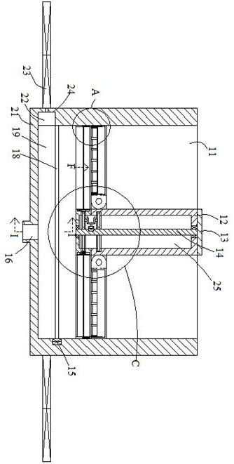
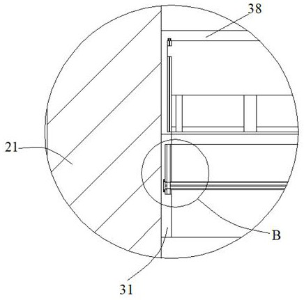
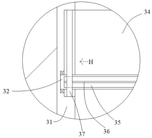
[0026] Such as Figure 1-Figure 10 As shown, the present invention is described in detail. For the convenience of description, the orientations mentioned below are now stipulated as follows: figure 1 The up, down, left, right, front and back directions of the projection relationship itself are consistent. A vertical injection molding machine of the present invention includes a matching box 21, an inner cavity 11 is arranged inside the matching box 21, and an inner cavity 11 is arranged on the end wall of the inner cavity 11. A motor 15, one side of the internal motor 15 is connected with a drive shaft 18, and the outer surface of the drive shaft 18 is rotated with a number of fixed connecting plates 19, and the end wall of the inner cavity 11 is connected with a side matching groove 24 , one side of the matching box 21 is provided with a push cylinder 23, and one side of the push rod of the push cylinder 23 is provided with a push plate 22, and the push plate 22 is set against...


PUM


Abstract

The invention discloses a vertical injection molding machine, comprising a matching box body. An inner cavity is formed in the matching box body, an inner motor is arranged in the end wall of the inner cavity, a driving shaft is arranged on one side of the inner motor in a power connection mode, a plurality of fixed connecting plates are rotationally arranged on the outer surface of the driving shaft, a side matching groove is formed in the end wall of the inner cavity in a communicating mode, a pushing cylinder is arranged on one side of the matching box body, a pushing plate is arranged on one side of a pushing rod of the pushing cylinder, the pushing plate abuts against the side matching groove, the pushing plate is opposite to the area between the fixed connecting plates, an extrusion hole is formed in the bottom of the inner cavity in a communicating mode, a plurality of plastic particles are arranged in the inner cavity, a guiding and chopping device for guiding and chopping the plastic particles is arranged in the inner cavity, and electric heating wires are arranged in the fixed connecting plates.

Description

technical field [0001] The invention relates to the technical field of injection molding equipment, in particular to a vertical injection molding machine. Background technique [0002] The existing vertical injection molding equipment directly has equipment that can melt the plastic during injection molding, and then directly transports it to the inside of the vertical injection molding equipment through pipelines. The main problem in this process is that because it is vertical Type injection molding equipment, and there is hot melt plastic flowing in the pipeline, then after it cools, it will be blocked in the pipeline. Although the existing technical solutions have a better way to solve this problem, it is not as good as how much plastic needs to be used. How much plastic is extruded after quantitative heating and hot-melting, and most of the existing plastics are extruded by direct melting of plastic particles, but plastic particles are difficult to heat and have strong a...

Claims


Application Information

Patent Timeline
IPC IPC(8): B29B13/02B02C18/10B02C18/18B02C18/24B29C31/06
CPCB29B13/022B02C18/10B02C18/18B02C18/24B29C31/06
Inventor 汪涛
Owner 汪涛
Learn More