Eureka AIR delivers breakthrough ideas for toughest innovation challenges, trusted by R&D personnel around the world.

Glass insulator compression molding device

A technology of glass insulators and press molding, which is applied in glass molding, glass pressing, glass manufacturing equipment, etc., can solve the problems of affecting electromechanical performance, poor heat dissipation effect of cooling device, poor cooling effect, etc., and achieve stable electromechanical performance and Excellent, improve work efficiency, improve the effect of dry arc distance

Pending Publication Date: 2021-12-10
江西泉新电气有限公司
View PDF6 Cites 1 Cited by
  • Summary
  • Abstract
  • Description
  • Claims
  • Application Information

AI Technical Summary

Problems solved by technology

However, in the prior art, the cooling process needs to be equipped with additional cooling tools, and the method of ejecting the workpiece is used when discharging, which has a certain impact on the surface of the workpiece; while the forming mold with heat dissipation function in the prior art, The cooling effect is poor and uneven, and the temperature difference of the forming mold can reach up to 300°C; coupled with the poor heat dissipation effect of the external cooling device of the forming mold, the electromechanical performance of the product is poor and the self-explosion rate is high
For example, the patent No. 201711330155.1 "Insulator Mold with Heat Dissipation Mechanism" has only one cooling air inlet, and there are defects in the design of the suction port and the internal branch air pipe. The cooling air will be partially sucked away before it reaches the surface of the insulator, resulting in The cooling effect is poor and the cooling is uneven; in addition, after the cooling is completed, the insulator workpiece is slightly sucked up by the suction pump, and then the workpiece is ejected from the bottom through the cylinder, and the surface of the workpiece is affected by the suction force and the ejection rigid force. Susceptible to breakage, affecting electromechanical performance

Method used


Image

  • Glass insulator compression molding device
  • Glass insulator compression molding device
  • Glass insulator compression molding device

Examples


Embodiment Construction

[0025] The technical solutions in the embodiments of the present invention will be clearly and completely described below in conjunction with the accompanying drawings in the embodiments of the present invention. Obviously, the described embodiments are only some of the embodiments of the present invention, not all of them. . Based on the embodiments of the present invention, all other embodiments obtained by persons of ordinary skill in the art without making creative efforts belong to the protection scope of the present invention.

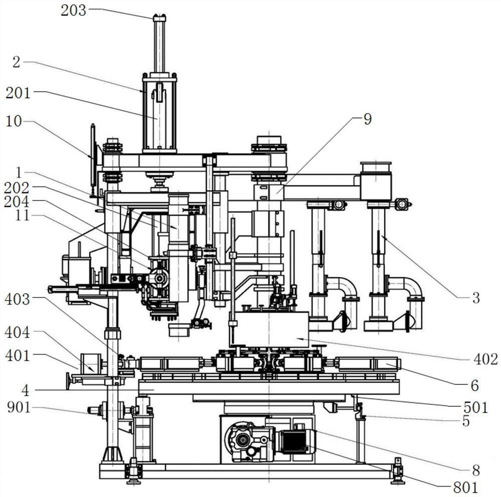
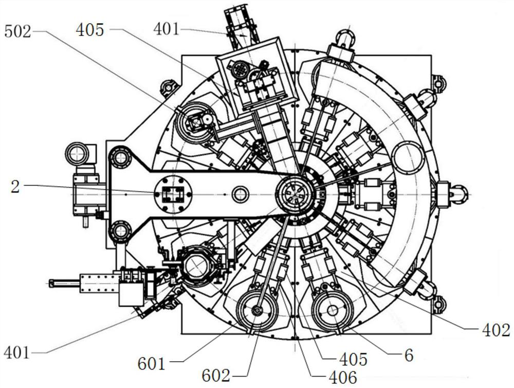
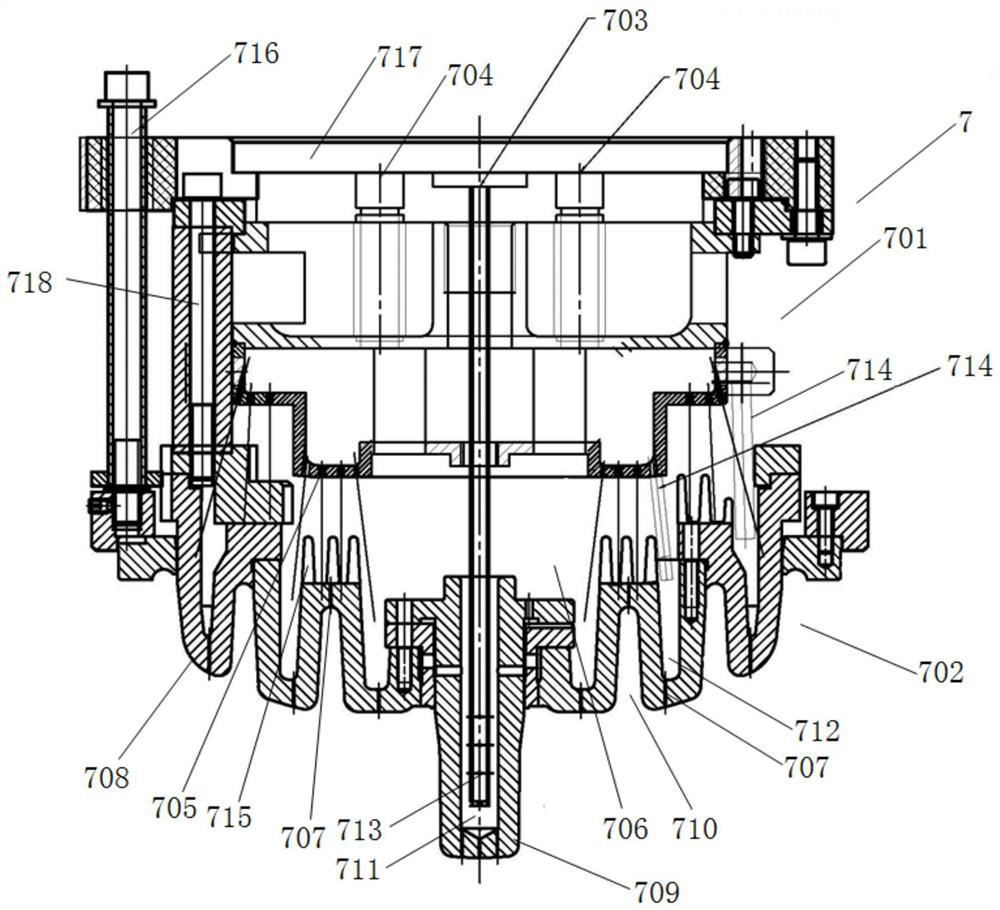
[0026] Such as Figure 1-5 As shown, the preferred embodiment of the present invention provides a press-forming device for glass insulators, including: a material guide mechanism 1, a stamping device 2, a cold blowing device 3, a turntable 4 and a turntable air inlet mechanism 5, and the turntable 4 is provided with There are a number of lower molds 6 distributed around the circumference, the lower end of the stamping device 1 is connected to th...


PUM


Abstract

The invention provides a glass insulator compression molding device, which comprises a material guide mechanism, a stamping device, a cold blowing device, a turntable and a turntable air inlet mechanism, the turntable is provided with a plurality of lower dies distributed circumferentially, the lower end of the stamping device is connected with an upper die, the material guide mechanism, the stamping device and the cold blowing device are arranged above the turntable, and an air outlet of the turntable air inlet mechanism is arranged below the turntable. A mold cooling system in compression molding is improved, heat can be effectively discharged, the temperature difference of the improved mold is smaller than 50 K, the dry arc distance can be effectively increased, the electromechanical performance of a product is more stable and excellent, and the spontaneous explosion rate of the product is effectively reduced. And the lower die is periodically moved by using the turntable, so that the compression molding, glass piece conveying and demolding operations are continuously carried out, and the working efficiency is greatly improved.

Description

technical field [0001] The invention relates to the technical field of insulator preparation, in particular to a press molding device for glass insulators. Background technique [0002] Insulators are an important part of overhead transmission lines and the most widely used components in power systems. Glass insulators have been widely used in transmission lines due to their good arc resistance and vibration resistance, not easy to aging and good self-cleaning properties. Glass insulators are generally composed of iron caps, tempered glass parts and steel feet, and are glued together with adhesives through glue mounting, curing and other processes. [0003] The insulating part of the glass insulator is formed by glass hydraulic pressure, and the press forming generally needs to be equipped with a suitable mold for molding. In compression molding, inject a certain amount of material into the female mold first, then close the mold part, wait for the material to be roughly fo...

Claims


Application Information

Patent Timeline
Patent Type & Authority Applications(China)
IPC IPC(8): C03B11/00C03B11/06C03B11/12
CPCC03B11/00C03B11/06C03B11/125
Inventor 梁旖旎陈利民刘长虹刘继辉李海萍
Owner 江西泉新电气有限公司
Why Eureka
Eureka Blog
Learn More