Crystal handle manufacturing process and crystal handle

A manufacturing process and handle technology, applied in the direction of leaf handles, leaf handles, door/window accessories, etc., can solve the problems of poor durability, easy degumming, poor reliability, etc., to improve surface roughness and contact points Density, the effect of improving reliability

Inactive Publication Date: 2021-12-10
胡淳龙
View PDF0 Cites 0 Cited by
  • Summary
  • Abstract
  • Description
  • Claims
  • Application Information

AI Technical Summary

Problems solved by technology

For the existing crystal handle, it generally includes a connecting seat and a crystal. The connecting seat is used to connect with the lock bar or rotating parts of the door lock. It is generally made of metal. The crystal and the connecting seat are generally bonded directly. The method of connecting together is too simple, and because the materials of the two are different, the connecting seat is metal, and the reliability of direct bonding is poor. When the crystal handle is used in daily use, its crystal is generally used as a tool for the user to grasp and rotate. Parts are used, after a long time of use, it is easy to deglue with the connecting seat, so that the connecting seat and the crystal are separated, and the durability is poor

Method used


Image

  • Crystal handle manufacturing process and crystal handle
  • Crystal handle manufacturing process and crystal handle
  • Crystal handle manufacturing process and crystal handle

Examples


Embodiment Construction

[0028] Embodiments of the present invention are described in detail below, examples of which are shown in the drawings, wherein the same or similar reference numerals designate the same or similar elements or elements having the same or similar functions throughout. The embodiments described below by referring to the figures are exemplary only for explaining the present invention and should not be construed as limiting the present invention.

[0029] In the description of the present invention, unless otherwise clearly defined, words such as setting, installation, and connection should be understood in a broad sense, and those skilled in the art can reasonably determine the specific meanings of the above words in the present invention in combination with the specific content of the technical solution.

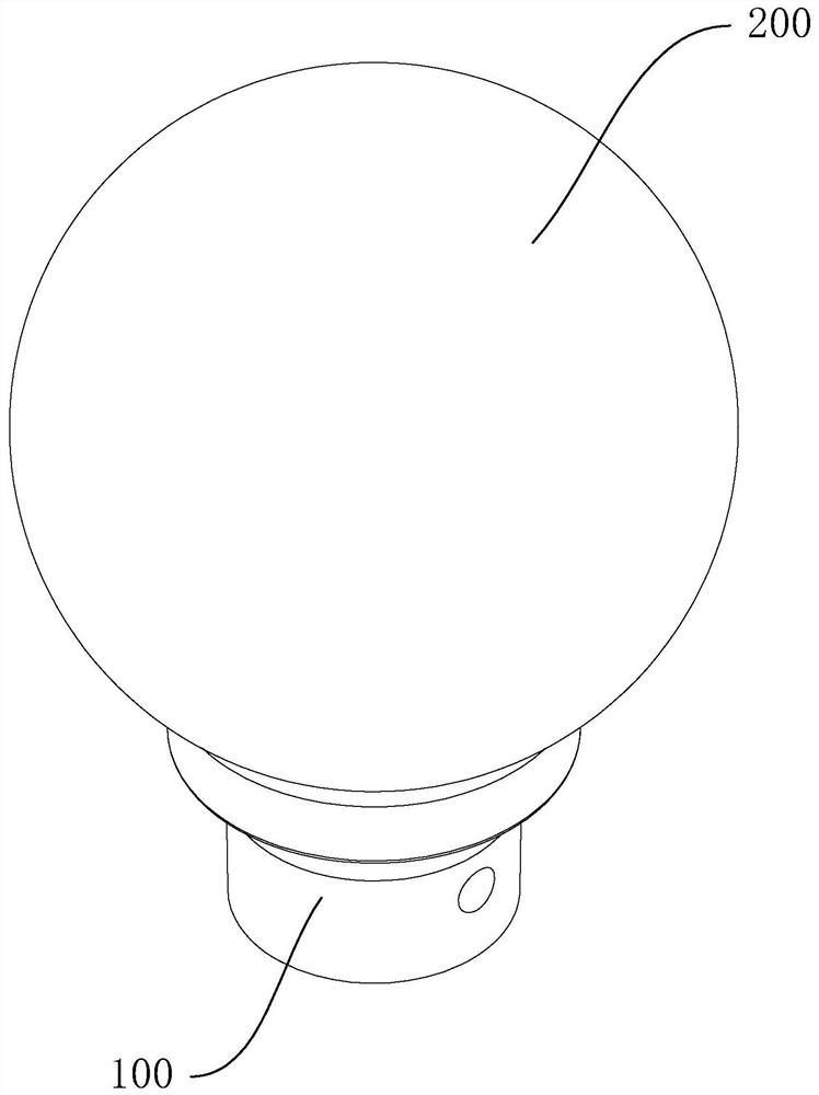
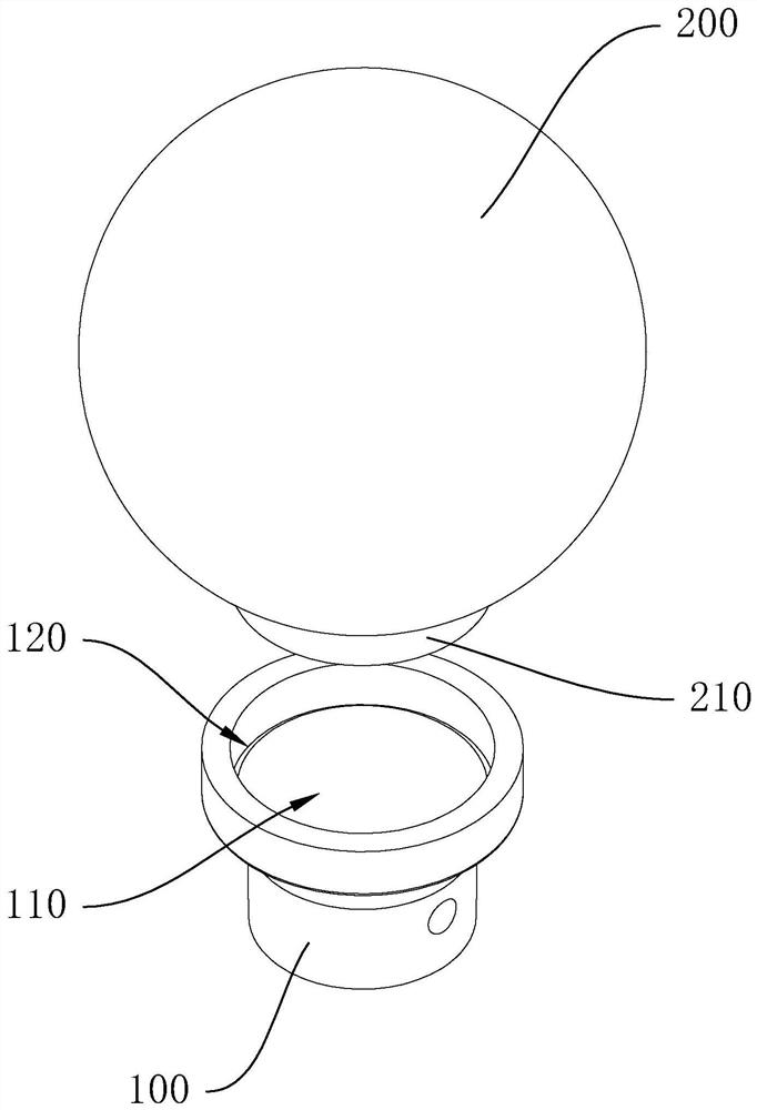
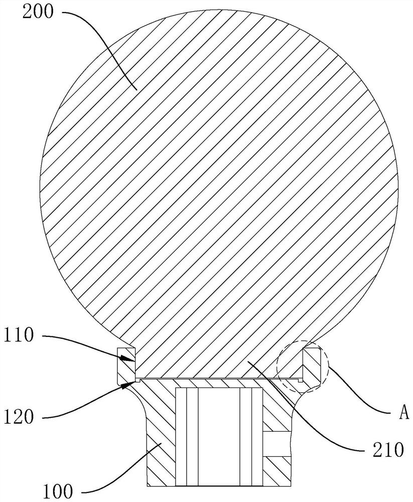
[0030] refer to figure 1 , figure 2 and image 3 , a crystal handle manufacturing process, the crystal handle includes a connecting base 100 and a crystal 200, the connectin...


PUM

PropertyMeasurementUnit
thicknessaaaaaaaaaa

Abstract

The invention discloses a crystal handle manufacturing process and a crystal handle. The crystal handle comprises a connecting base and a crystal body, wherein the connecting base is provided with a bonding groove, the crystal body is provided with a boss, scratches are formed on the inner wall face of the bonding groove, the boss is inserted into the bonding groove, and an adhesive layer is arranged between the boss and the bonding groove. The inner wall surface of the bonding groove is connected with the outer surface of the boss through a bonding layer; the crystal handle manufacturing process comprises the following steps of forming the scratches, wherein the scratches are formed on the inner wall face of the bonding groove; and bonding connection, wherein the inner wall face of the bonding groove and/or the outer surface of the boss are/is coated with an adhesive, and the boss is inserted into the bonding groove so that the inner wall face of the bonding groove and the outer surface of the boss can be bonded through the adhesive. By making the scratches on the inner wall face of the bonding groove, the surface roughness of the inner wall face of the bonding groove can be improved, the contact point density of the adhesive and a connecting base is improved, and therefore, the bonding strength between the connecting base and the crystal body can be improved.

Description

technical field [0001] The invention relates to the technical field of door locks, in particular to a crystal handle manufacturing process and the crystal handle. Background technique [0002] For existing door locks, some door locks are required for aesthetics, and their handles are usually made of crystal material. For the existing crystal handle, it generally includes a connecting seat and a crystal. The connecting seat is used to connect with the lock bar or rotating parts of the door lock. It is generally made of metal. The crystal and the connecting seat are generally bonded directly. The method of connecting together is too simple, and because the materials of the two are different, the connecting seat is metal, and the reliability of direct bonding is poor. When the crystal handle is used in daily use, its crystal is generally used as a tool for the user to grasp and rotate. Parts are used, after a long period of use, it is easy to deglue between it and the connecti...

Claims


Application Information

Patent Timeline
Patent Type & Authority Applications(China)
IPC IPC(8): E05B1/00
CPCE05B1/0007
Inventor 胡淳龙
Owner 胡淳龙
Why Eureka
Try Eureka