
lighting device for motorcycle

A technology for lighting devices and motorcycles, which is applied to lighting devices, components of lighting devices, signal devices, etc., and can solve the problems of the influence of LED lamp beads on the luminous effect, the inability to meet the consistency of motorcycle lighting devices and the overall luminous effect, etc. Achieve the effect of improving waterproof level and improving light efficiency

Active Publication Date: 2022-02-11
深圳市金风驰科技有限公司
View PDF5 Cites 0 Cited by
  • Summary
  • Abstract
  • Description
  • Claims
  • Application Information

AI Technical Summary

Problems solved by technology

Usually to change or refit the motorcycle lighting device, the shape of the motorcycle lighting device should be determined according to the existing structure of the motorcycle. For example, when it comes to elongated or narrow motorcycle lighting devices, the motorcycle lighting device Arranging the LED lamp beads on the PCB in a narrow place should not only meet the overall lighting effect, but also ensure the waterproof performance of the entire motorcycle lighting device. However, for the narrow and long motorcycle lighting device, the above-mentioned requirements, for the PCB board arranged in the narrow place of the motorcycle lighting device, the glue will be squeezed onto the PCB when injecting glue, which will affect the luminous effect of the LED lamp beads. If the width of the PCB board is shortened, the layout will be waterproof The glue tank cannot satisfy the consistency of the overall lighting and the overall luminous effect of the motorcycle lighting device

Method used

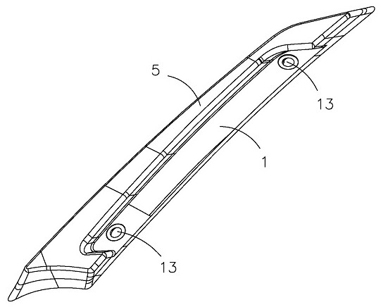
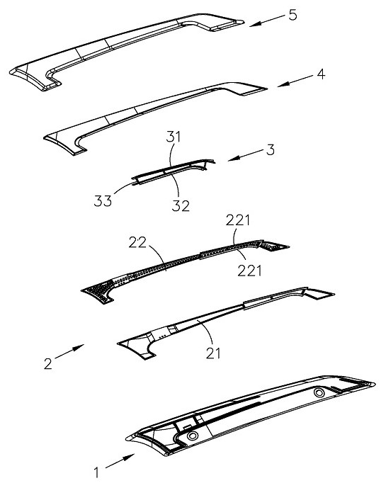
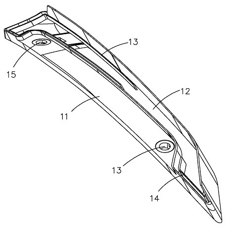

Image

  • lighting device for motorcycle
  • lighting device for motorcycle
  • lighting device for motorcycle

Examples


Embodiment Construction

[0020] In order to facilitate the understanding of the present invention, the present invention will be described more fully below with reference to the associated drawings. Preferred embodiments of the invention are shown in the accompanying drawings. However, the present invention can be embodied in many different forms and is not limited to the embodiments described herein. On the contrary, the purpose of providing these embodiments is to make the disclosure of the present invention more thorough and comprehensive.

[0021] It should be noted that when an element is considered to be "connected" to another element, it may be directly connected to the other element or there may be intervening elements at the same time. The terms "vertical," "horizontal," "left," "right," and similar expressions are used herein for purposes of illustration only and are not intended to represent the only embodiments.

[0022] Unless otherwise defined, all technical and scientific terms used h...


PUM


Abstract

The motorcycle lighting device of the present invention comprises a base, an LED lamp board, a bridging structure, a diffuser plate and a lampshade, the base is provided with a strip-shaped installation groove, and the LED lamp board is installed at the bottom of the installation groove, The bridging structure abuts against both ends of the LED light board, the two ends of the diffusion plate abut the bridging structure respectively, the lampshade is arranged on the diffusion plate, and the groove wall of the installation groove The first storage tank and the second storage tank are surrounded by the bridging structure, and the two ends of the lampshade are respectively inserted into the first storage tank and the second storage tank; Leave space to arrange the components on the PCB board, and install the LED light board on the fixed-size base; at the same time, the outer side of the bridge structure and the inner wall of the base form a waterproof glue groove, which is convenient for glue injection to fix the lampshade, and the waterproof level is improved to IP67.

Description

technical field [0001] The invention relates to the technical field of motorcycle lighting, in particular to a motorcycle lighting device. Background technique [0002] Existing motorcycle lighting devices generally include a lamp holder, an LED light source, an optical lens and a lampshade. The light source performs secondary optical imaging, and the lampshade shines on the optical lens. Usually to change or refit the motorcycle lighting device, the shape of the motorcycle lighting device should be determined according to the existing structure of the motorcycle. For example, when it comes to elongated or narrow motorcycle lighting devices, the motorcycle lighting device Arranging the LED lamp beads on the PCB in a narrow place should not only meet the overall lighting effect, but also ensure the waterproof performance of the entire motorcycle lighting device. However, for the narrow and long motorcycle lighting device, the above-mentioned requirements, for the PCB board ...

Claims


Application Information

Patent Timeline
Patent Type & Authority Patents(China)
IPC IPC(8): F21S41/19F21S41/141F21V3/02F21S45/50F21S41/37F21Y115/10F21W107/17
CPCF21S41/19F21S41/141F21V3/02F21S45/50F21S41/37F21Y2115/10F21W2107/17
Inventor 黄锦洪王红印李明
Owner 深圳市金风驰科技有限公司
Learn More