High-precision medium-thickness plate width measuring method based on machine vision

A width measurement and machine vision technology, applied in measurement devices, instruments, genetic models, etc., can solve the problems of not taking into account the small angle deviation of the camera, unable to adapt to steel plate width detection, limited camera accuracy, etc., to achieve extended accuracy and detection range. Effect

Active Publication Date: 2021-12-10
UNIV OF SCI & TECH BEIJING
View PDF23 Cites 0 Cited by
  • Summary
  • Abstract
  • Description
  • Claims
  • Application Information

AI Technical Summary

Problems solved by technology

This method generally uses a single area array camera for image acquisition, and the accuracy of the camera is limited, so it is difficult to achieve high-precision measurement
[0003] It is mentioned in the prior art that the dual-CCD detection method is used, and the strip width is obtained by measuring the difference between the projection points of the two boundary points on the two cameras and using the geometric relationship. This method cannot adapt to the detection of the steel plate width in a large width range. The accuracy is limited, and at the same time, the small angle deviation of the camera installation is not considered, and there will be nonlinear errors in measurement
There is also a method to install a line array camera above and below the strip to detect the edge of the strip. Although the problem of angle deviation in the multi-camera solution is avoided, a single camera limits the detection accuracy of the final strip width.

Method used


Image

  • High-precision medium-thickness plate width measuring method based on machine vision
  • High-precision medium-thickness plate width measuring method based on machine vision
  • High-precision medium-thickness plate width measuring method based on machine vision

Examples


Embodiment Construction

[0035] In order to make the technical problems, technical solutions and advantages to be solved by the present invention clearer, the following will describe in detail with reference to the drawings and specific embodiments.

[0036] The invention provides a machine vision-based method for measuring the width of a medium-thick plate with high precision.

[0037] like figure 1 As shown, the method includes the following steps:

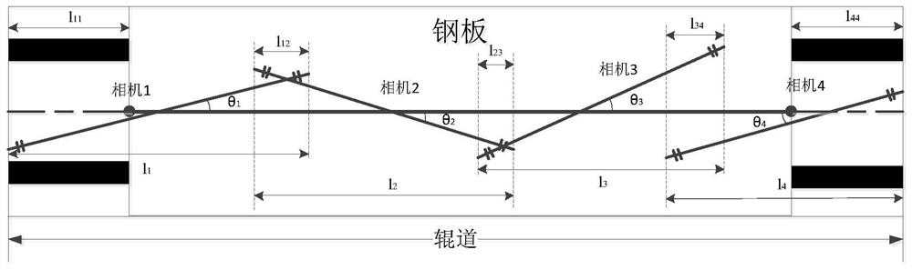
[0038] (1) Multiple line array cameras are distributed along the width direction of the steel plate on the same horizontal line to collect images of the lower surface of the steel plate, and the shooting range of each camera overlaps to a certain extent;

[0039] (2) According to the data calibrated by the cameras, remove the overlapping pixels of the shooting areas between the cameras;

[0040] (3) Segment the pixels representing the steel plate in each camera image, and combine the actual resolution of the camera to obtain the actual steel plate range...


PUM


Abstract

The invention provides a high-precision medium-thickness plate width measuring method based on machine vision, and belongs to the technical field of machine vision detection. According to the method, multiple linear array cameras are distributed on the same horizontal line in the width direction of a steel plate to collect lower surface images of a steel plate; the resolutions of the cameras and the overlapping area between the cameras are calibrated through a calibration plate, and the actual steel plate shooting range of the cameras is obtained by removing the overlapping area, the background area and other redundant areas; and the optimal deflection angle solution of each camera is fit through a genetic algorithm, the projection length of the steel plate shooting range of each camera in the width direction of the steel plate is calculated by using the deflection angle, and the projection lengths are accumulated to obtain the width value of the steel plate. According to the method, the width measurement range can be expanded, the problems of insufficient precision, fuzzy boundary and the like existing in measurement of a single camera are avoided, nonlinear errors in the measurement process are greatly reduced, and the width measurement precision is obviously improved.

Description

technical field [0001] The invention relates to the technical field of machine vision detection, in particular to a machine vision-based high-precision medium-thick plate width measurement method. Background technique [0002] Steel plate width measurement is an indispensable detection process in the steel production process. At present, the commonly used width measurement methods mostly use the combination of laser and area array camera to obtain images and analyze the boundary information, and then use the corresponding positions of boundary pixels and objects The relationship gets the width of the steel plate. This method generally uses a single area array camera for image acquisition, and the camera has limited precision, making it difficult to achieve high-precision measurement. [0003] It is mentioned in the prior art that the dual-CCD detection method is used, and the strip width is obtained by measuring the difference between the projection points of the two bounda...

Claims


Application Information

Patent Timeline
Patent Type & Authority Applications(China)
IPC IPC(8): G01B11/02G06N3/12G06T7/73G06T7/80
CPCG01B11/022G06T7/73G06T7/80G06N3/126Y02P90/30
Inventor 吴昆鹏孙文权杨朝霖
Owner UNIV OF SCI & TECH BEIJING
Why Eureka
Try Eureka