
Quantum current transformer

A current transformer, quantum technology, applied in the measurement of current/voltage, measurement of electrical variables, phase angle between voltage and current, etc., can solve the problems of narrow dynamic range, small measurement bandwidth, large size, etc., to enhance safety. sexual effect

Pending Publication Date: 2021-12-10
JIANGSU SIYUAN HERTZ TRANSFORMER +2
View PDF0 Cites 4 Cited by
  • Summary
  • Abstract
  • Description
  • Claims
  • Application Information

AI Technical Summary

Problems solved by technology

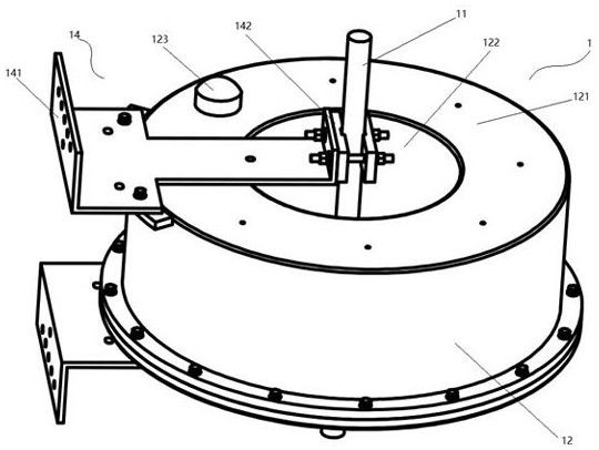
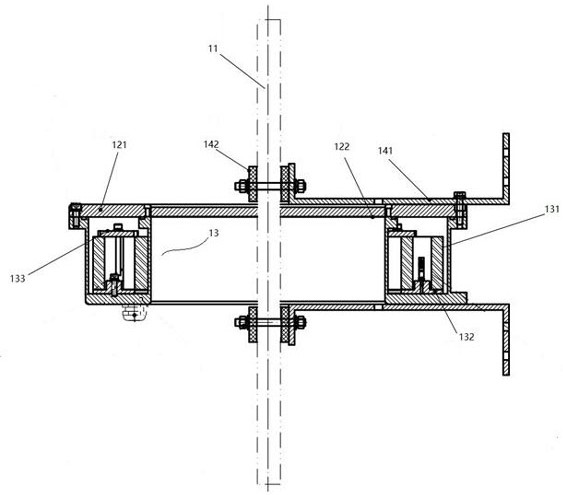
class="d_n">[0006] The technical problem to be solved by the present invention is to provide a quantum current transformer, which can solve the problems of small measurement bandwidth, narrow dynamic range, bulky size and high energy loss of general electromagnetic transformers

Method used


Image

  • Quantum current transformer
  • Quantum current transformer
  • Quantum current transformer

Examples


Embodiment Construction

[0021] In order to make the purpose, technical solutions and advantages of the embodiments of the present invention clearer, the technical solutions in the embodiments of the present invention will be clearly and completely described below in conjunction with the drawings in the embodiments of the present invention. Obviously, the described embodiments It is a part of embodiments of the present invention, but not all embodiments. The components of the embodiments of the invention generally described and illustrated in the figures herein may be arranged and designed in a variety of different configurations.

[0022] Accordingly, the following detailed description of the embodiments of the invention provided in the accompanying drawings is not intended to limit the scope of the claimed invention, but merely represents selected embodiments of the invention. Based on the embodiments of the present invention, all other embodiments obtained by persons of ordinary skill in the art wi...


PUM


Abstract

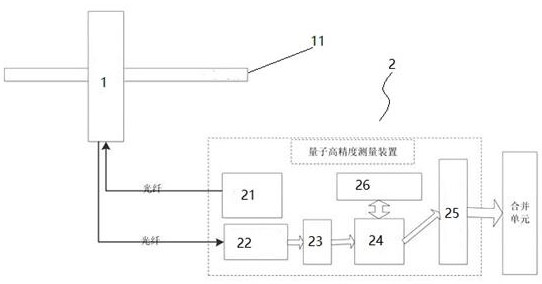
The invention relates to a quantum current transformer. The quantum current transformer is characterized by comprising a quantum sensor and a quantum measurement module, wherein the quantum sensor and the quantum measurement module are connected through an optical fiber to form a loop. The NV color center has the characteristics of high sensitivity and high frequency response of magnetic measurement, so that the current can be measured in a continuous wave magnetic side environment; the high-sensitivity magnetic sensor can accurately measure current signals in a power grid, so that high-precision current amplitude and phase information is obtained, and the high-sensitivity magnetic sensor is of great significance to operation management of the power grid. Secondly, the magnetic sensor with a high frequency response range can monitor the distribution of high-frequency impact signals in the power grid, the safety state of the power grid is monitored while the current of the power grid is measured, and the safety of the power grid is enhanced.

Description

technical field [0001] The invention relates to the technical field of current mutual inductance, in particular to a quantum current transformer. Background technique [0002] With the continuous expansion of the scale of the power grid, the requirements of the power grid system for the safety, reliability and versatility of the equipment used are also increasing. Taking the current transformer of the power grid system as an example, the traditional electromagnetic current transformer uses the principle of electromagnetic induction to measure the current intensity. It has been continuously improved and optimized in long-term practice, and has made great contributions to social development. However, with the increase of the grid scale and the improvement of technical indicators, the electromagnetic transformer technology gradually shows the bottleneck of various technical indicators, such as small measurement bandwidth, narrow dynamic range, large volume, high energy loss and...

Claims


Application Information

Patent Timeline
Patent Type & Authority Applications(China)
IPC IPC(8): G01R19/00G01R25/00G01R31/08
CPCG01R19/00G01R25/00G01R31/086
Inventor 赵龙周宪林唐陈王鑫仇茹嘉王丽君翟玥张韦吴海龙张华友王宁
Owner JIANGSU SIYUAN HERTZ TRANSFORMER
Learn More