Eureka AIR delivers breakthrough ideas for toughest innovation challenges, trusted by R&D personnel around the world.

Magnetizing permanent magnets

A permanent magnet, magnetic field technology, applied in the direction of magnetic objects, magnetic circuits, permanent magnets, etc., can solve problems such as incomplete magnetization

Pending Publication Date: 2021-12-10
GENERAL ELECTRIC RENOVABLES ESPANA SL
View PDF1 Cites 0 Cited by
  • Summary
  • Abstract
  • Description
  • Claims
  • Application Information

AI Technical Summary

Problems solved by technology

This post magnetization generally requires a strong magnetic field and a lot of energy, and the magnetization may still be incomplete

Method used


Image

  • Magnetizing permanent magnets
  • Magnetizing permanent magnets
  • Magnetizing permanent magnets

Examples


Embodiment Construction

[0059] Reference will now be made in detail to embodiments of the invention, one or more examples of which are illustrated in the accompanying drawings. Each example is provided by way of explanation of the invention, not limitation of the invention. In fact, it will be apparent to those skilled in the art that various modifications and variations can be made in the present disclosure without departing from the scope or spirit of the invention. For example, features illustrated or described as part of one embodiment can be used with another embodiment to yield a still further embodiment. Thus, it is intended that the present invention covers such modifications and variations as come within the scope of the appended claims and their equivalents.

[0060] In these figures, the same reference numerals have been used to denote matching elements.

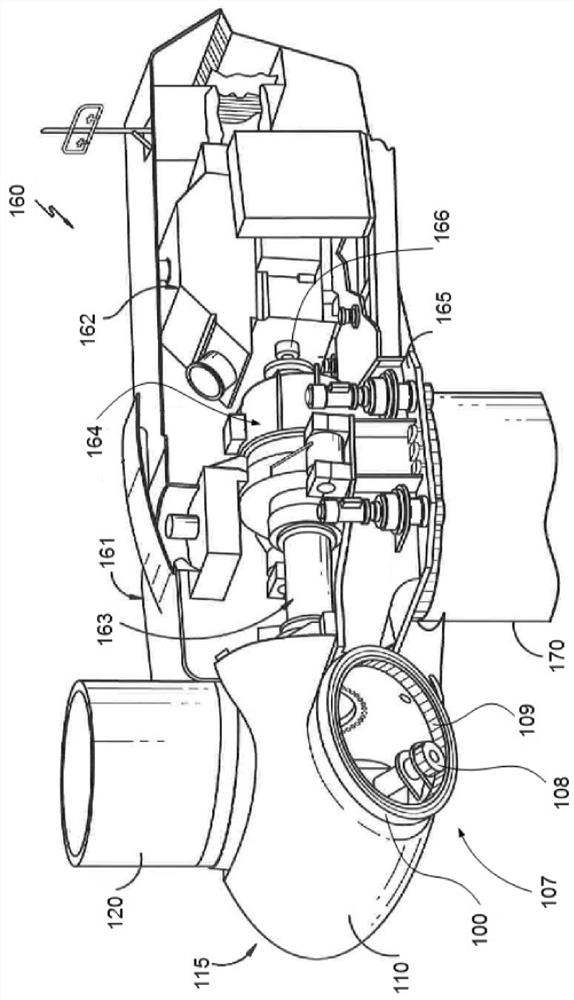
[0061] figure 1 A perspective view of one example of a wind turbine 160 is shown. As shown, wind turbine 160 includes a tower 170 e...


PUM


Abstract

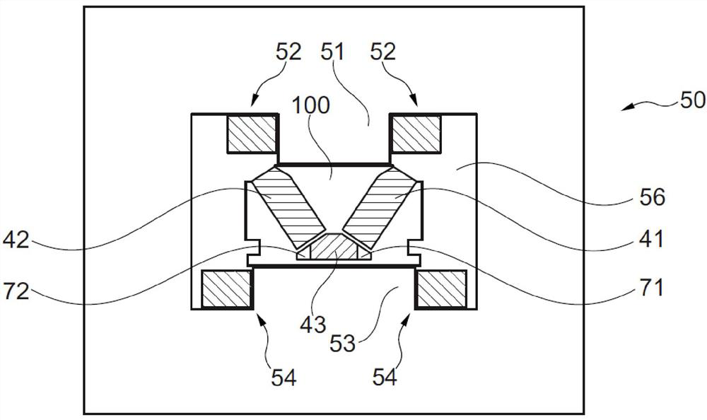
The invention relates to magnetizing permanent magnets. A method for magnetizing a section of one or more permanent magnets arranged substantially in a V-shape, comprises: applying a first magnetic field such that magnetic flux lines are substantially perpendicular to a first leg of the V-shape, and removing the first magnetic field. Then the method comprises applying a second magnetic field such that magnetic flux lines are substantially perpendicular to a second leg of the V-shape, and removing the second magnetic field. Systems and methods for magnetizing sections of permanent magnet modules are also provided.

Description

technical field [0001] The present disclosure relates to methods and systems for magnetizing permanent magnets. The present disclosure relates in particular to methods and systems for magnetizing permanent magnet modules for electric machines, in particular generators, and more particularly wind turbine generators. Background technique [0002] Electrical machines, such as motors and generators, generally include a rotor structure and a stator structure. In the case of an electric machine employing permanent magnets, the permanent magnets (PM) are generally contained in the rotor (although they could alternatively be arranged in the stator structure), while the winding elements (e.g. coils) are usually contained in the stator ( Although they could alternatively be arranged in the rotor structure). [0003] In the case of a PM generator, the rotation of the rotor structure under the influence of an external force produces a changing magnetic field in the windings, from whic...

Claims


Application Information

Patent Timeline
IPC IPC(8): H01F13/00
CPCH01F13/003H02K15/03H02K1/2766H02K7/1838H02K2213/12H02K2213/03Y02E10/72H01F7/02F03D9/25F05B2220/706H02K7/116H02K21/22
Inventor J·C·乌雷斯蒂M·阿瓦尼索夫C·穆尼兹卡塞斯N·加勒斯拉文托斯
Owner GENERAL ELECTRIC RENOVABLES ESPANA SL
Why Eureka
Eureka Blog
Learn More