

Laser discharge cavity electrode loss compensable structure
A technology of electrode loss and compensation structure, applied in the field of lasers, can solve the problems of uneven material, large loss, unevenness, etc., and achieve the effects of quick replacement, low cost and simple method
- Summary
- Abstract
- Description
- Claims
- Application Information
AI Technical Summary
Problems solved by technology
Method used
Image

Examples
Embodiment 1
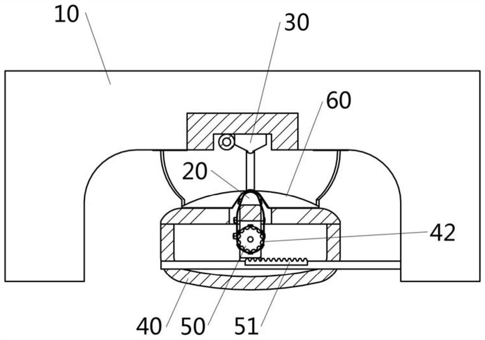
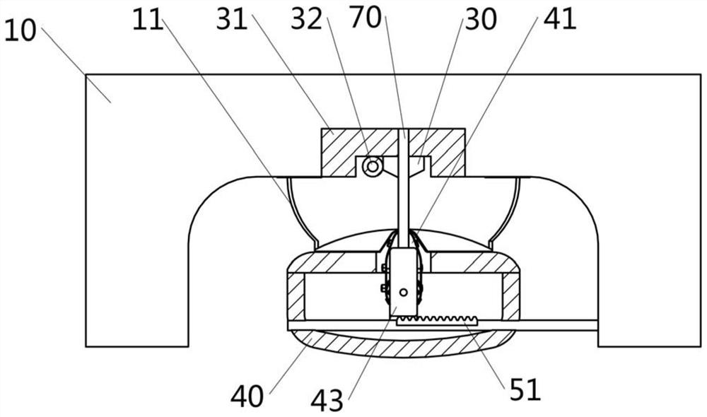
[0055] like Figure 1-7 Design, a laser discharge chamber electrode loss can compensate for a cavity 10, including a cavity 10 of a discharge chamber; a first electrode 20 and a second electrode 30; first electrode 20 and The polarity of the secondary electrode 30 is opposite; specifically, in the present embodiment, the second electrode 30 is a cathode, and the first electrode 20 is an anode. Wherein, the second electrode 30 is fixed to the side wall of the cavity 10 through the cathode base 31. A pre-ion zone structure 32 is provided near the second electrode 30. A refill sheet 11 is provided on both sides of the first electrode 20 and the second electrode 30.
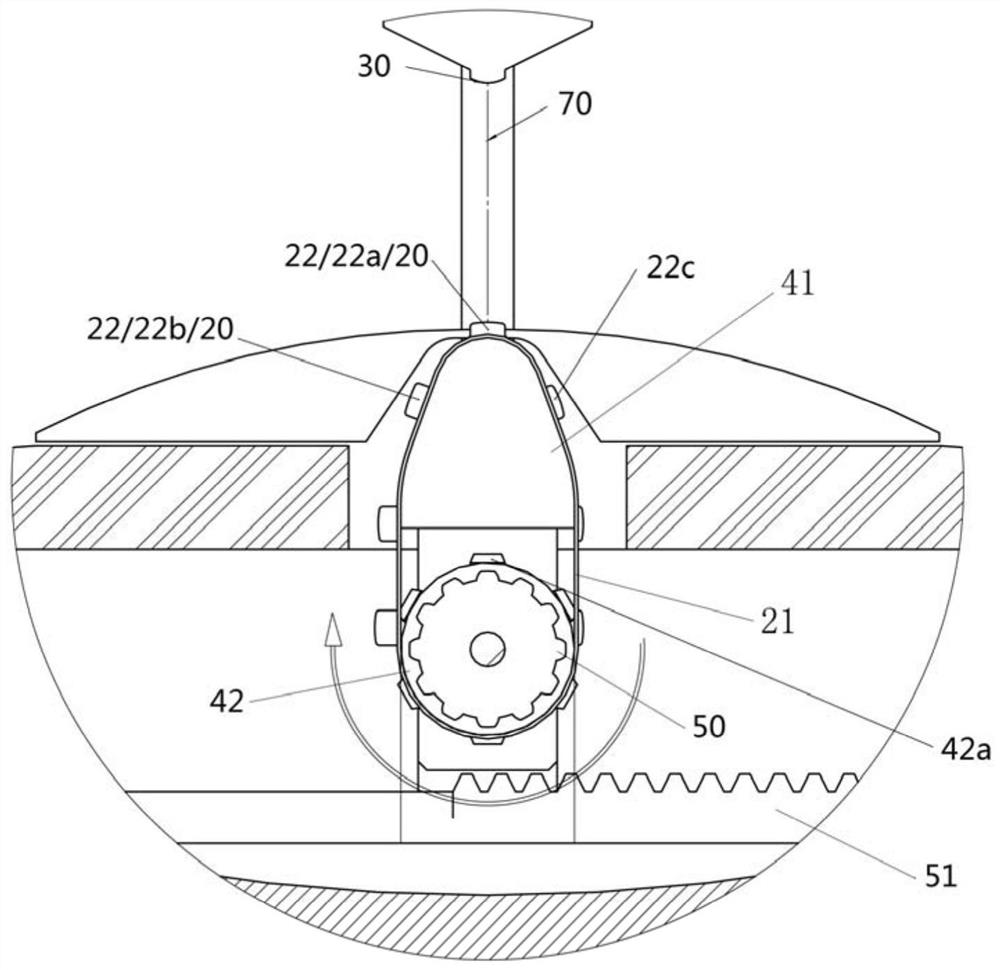
[0056] like image 3 As shown, the first electrode 20 includes an annular baseband 21, and the annular baseband 21 is integrally a sleeve shape, and on a cross section perpendicular to the length of the first electrode 20, the annular baseband 21 is annular to facilitate rotatable settings.
[0057] A plurality of electrod...
Embodiment 2
[0082] The compensation structure of the laser discharge chamber electrode loss provided in this example is substantially the same as the first embodiment, and the difference is:
[0083] like Figure 8 As shown, the left ceramic flow sheet 61 and the right ceramic flow slicer 62 can be disposed on the bracket 40. The two flow slices can be displayed, and thereby, the strip slit width between the two can be adjusted, and the electrode strip 22 is supplied to the electrode strip 22 when the rotary ring base belt 21 is rotated, and the electrode strip 22 and the ready-to-enter work are avoided. The electrode strip 22 of the state is interfered with the left ceramic flow sheet 61 or the right ceramic flow sheet 62. When the electrode strip 22 is replaced in place, the movable ceramic flow sheet moves to the intermediate, reduces the width of the strip slot, and even holds the electrode strip 22 in the middle of the two.
[0084] As a result, the drive mechanism of the shaft 42 may als...
Embodiment 3
[0087] The compensation structure of the laser discharge chamber electrode loss provided in this example is basically the same as that of Example 1 or Example 2, and the difference is:
[0088] The second electrode 30 is the same as the first electrode 20. The second electrode 30 is configured with the first electrode 20, that is, the second electrode 30 is provided with the first electrode 20, and the electrode strip 21, the electrode strip 22, and the corresponding drive mechanism, such as the two electrodes can be realized. Self-compensation.
PUM
 Abstract
Description
Claims
Application Information