
Bracket and method for fixing wire rod in bracket

A fixation method and wire technology, applied in stents, medical science, prosthesis, etc., can solve problems such as shape deformation, no research, insufficient expansion force, etc.

Pending Publication Date: 2021-12-10
PENTAS INC
View PDF1 Cites 0 Cited by
  • Summary
  • Abstract
  • Description
  • Claims
  • Application Information

AI Technical Summary

Problems solved by technology

[0004] Usually, in a stent of braided wires, since the wires are not fixed to each other and are independent, there is a possibility of fraying at both ends and deformation of the shape when manufacturing the stent
In addition, wire deflection sometimes occurs within the catheter during delivery of the stent
Furthermore, when the stent is expanded, the expansion force may be insufficient only by expansion utilizing the elasticity of the wire.
However, conventionally, no research has been conducted on techniques for solving these problems

Method used


Image

  • Bracket and method for fixing wire rod in bracket
  • Bracket and method for fixing wire rod in bracket
  • Bracket and method for fixing wire rod in bracket

Examples


Embodiment Construction

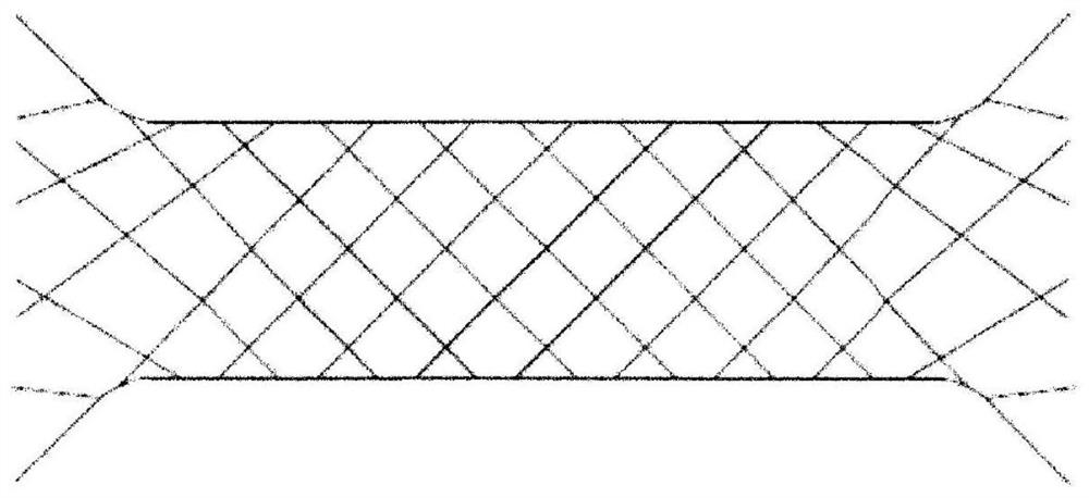
[0025] figure 1 is a schematic diagram showing the shape of a stent. In this embodiment, if figure 1 As shown, it is assumed that multiple wires are woven into a helical scaffold. For the element wire, metal materials such as stainless steel, Co—Cr alloy (cobalt chromium alloy), and Ni—Ti alloy (nickel titanium alloy) are used.

[0026] The stent is formed by weaving a plurality of metal wires in a spiral shape in this way, and there are various types of wires constituting the stent. For example, there are stents with a 16-wire structure in which 16 wires are braided, a stent with a 24-wire structure in which 24 wires are braided, a stent with a 32-wire structure in which 32 wires are braided, and the like. In addition, in figure 1 A scaffold of 16 structures is shown in .

[0027] In such a stent formed by braiding a plurality of metal wires in a helical shape, usually the two ends of the wires are not fixed and independent, so as figure 2 As shown, fraying at both end...


PUM


Abstract

The invention provides a bracket and a method for fixing a wire rod in the bracket. The bracket is used for fixing a crossed part of the bracket. In a stent formed by weaving a plurality of wire rods into a spiral shape, at the intersecting parts of the wire rods, two intersecting wire rods are fixed by a fixing material having rubber elasticity.

Description

technical field [0001] The invention relates to a bracket and a method for fixing wires in the bracket. Background technique [0002] The following medical stents are known to the public. The stent is formed by braiding a plurality of wires in a helical shape (refer to Patent Document 1). [0003] Patent Document 1: Japanese Patent Laid-Open Publication No. 2012-223209 [0004] Generally, in a stent of braided wires, since the wires are not fixed to each other but are independent, fraying at both ends may occur during the manufacture of the stent and the shape may be deformed. In addition, when the stent is delivered, the wire may be misaligned in the catheter. Furthermore, when the stent is expanded, the expansion force may be insufficient only by expansion utilizing the elasticity of the wire. However, conventionally, no research has been conducted on techniques for solving these problems. Contents of the invention [0005] According to a first aspect of the present...

Claims


Application Information

Patent Timeline
Patent Type & Authority Applications(China)
IPC IPC(8): A61F2/88A61F2/89
CPCA61F2/88A61F2/90A61F2250/0018A61F2220/0025A61F2220/005A61F2/89A61F2210/0004A61F2210/0014
Inventor 西岸诚
Owner PENTAS INC
Learn More