Punching equipment for metal toothpick box cover

A box cover and toothpick technology, which is applied in metal processing equipment, pushing equipment, grinding/polishing equipment, etc., can solve the problems of reducing work efficiency, requiring a lot of effort, and the surface of the toothpick box cover is hard, so as to improve work efficiency. Effect

Pending Publication Date: 2021-12-14
徐涛
View PDF0 Cites 0 Cited by
  • Summary
  • Abstract
  • Description
  • Claims
  • Application Information

AI Technical Summary

Problems solved by technology

[0002] After eating, most people like to pick their teeth with toothpicks. Toothpicks are usually placed in the toothpick box and taken out of the toothpick box when used. Therefore, small holes need to be opened on the toothpick box cover. Now the method of opening holes It is to use a hole opener to punch holes in the top of the toothpick box cover one by one. The surface of the toothpick box cover made of metal is relatively hard, so people need to spend a lot of effort to complete it when punching holes, which will make people's hands sore and reduce work. efficiency

Method used


Image

  • Punching equipment for metal toothpick box cover
  • Punching equipment for metal toothpick box cover
  • Punching equipment for metal toothpick box cover

Examples


Embodiment 1

[0026] Toothpick metal punching apparatus for cover, such as Figure 1-3 Shown, comprises a bottom plate 1, frame 2 is placed, the mounting plate 3, the first bracket 4, a cylinder 5, the punch 6, the tool 7, 8 and the waste collection mechanism pusher mechanism 9, the base plate 1 is connected to frame 2 are placed, is placed 2 is connected to the top frame mounting plate 3, a top plate 3 is provided with a first mounting bracket 4, the bracket 4 is provided on the first cylinder 5, the cylinder 5 is provided with a bottom punch 6, a bottom tool 6 is provided with the right punch 7, a base plate, the mounting plate is provided between the waste collection means 78 and the tool 3, the ejector mechanism 9 is provided between a right side plate 3 and the mounting plate.

[0027] Waste collection mechanism 8 comprises a fixed block 80, a first spring 81, the mounting block 82, the slide plate 83 and collection tank 84, the left side of the base plate 1 is provided with the collecting ...

Embodiment 2

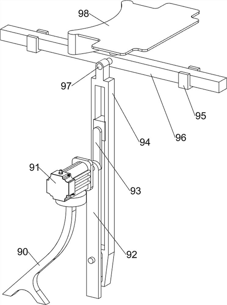
[0031] On the basis of Example 1, such as Figure 4-8 As shown in further comprising feeding mechanism 10, feeding mechanism 10 comprises a guide plate 100, the arcuate plate 101 and the hollowed hollow cylinder 102, the front and rear sides of the top mounting plate 3 are connected with a guide plate 100, the right guide plate 100 is connected between the hollow arcuate plate 101, top plate 101 is provided with an arcuate hollow cylinder 102 hollow.

[0032] When people need feeding, toothpick cover may be placed within the hollow arcuate plate 101, so that the drive interval toothpick cover Ejector 98 is moved left and right to the left, the guide plate 100 acts as a guide.

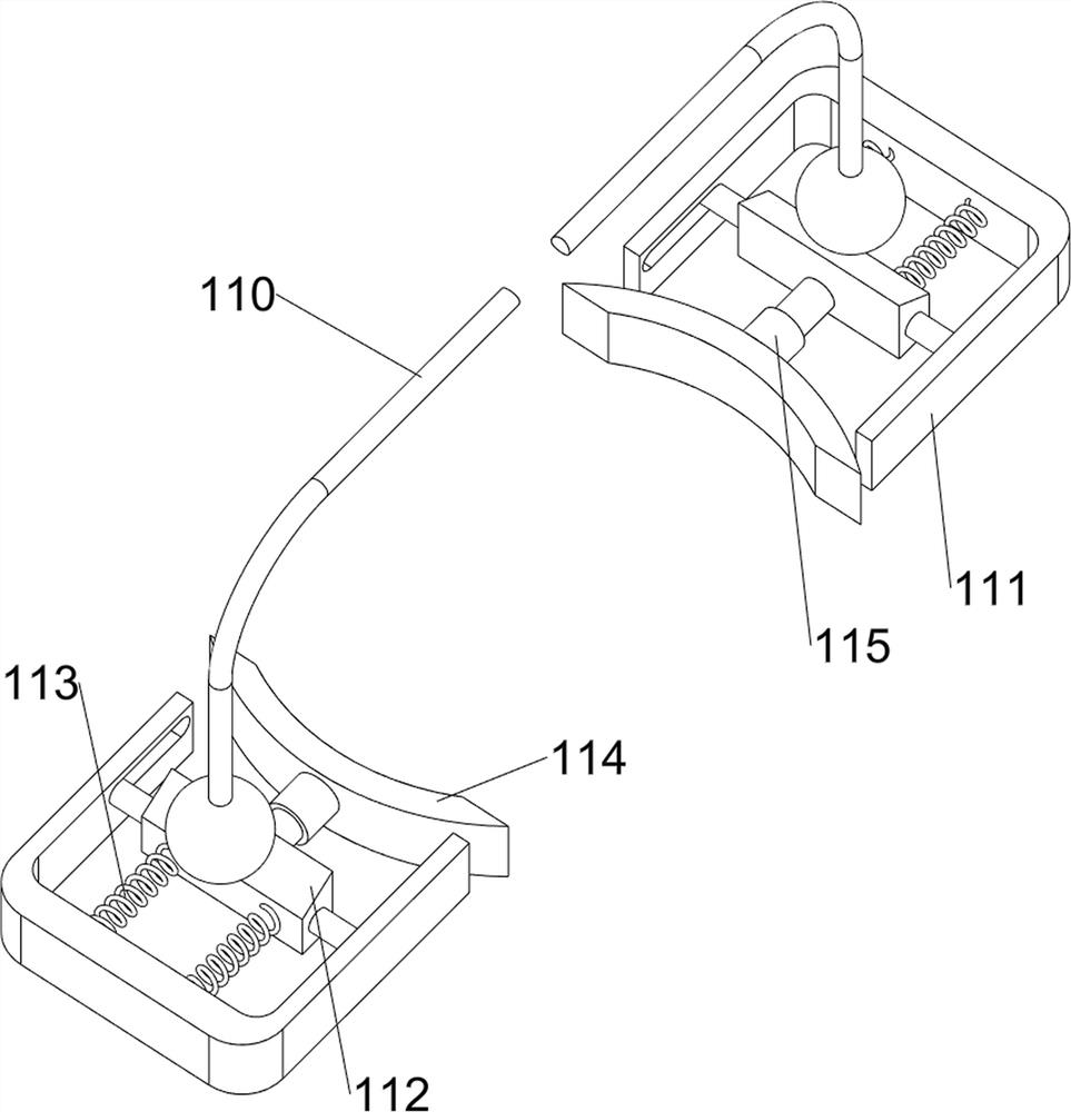
[0033] 3 further comprises a finite bit intermediate mechanism 11, the stopper mechanism 11 comprises a lever 110, a first slide rail 111, wedge 112, a second spring 113, a rubber plate 114, sleeve 115 and a third spring 116, mounting plate top front and top sides are connected with a first slide rail 111 ar...


PUM


Abstract

The invention relates to punching equipment, in particular to punching equipment for a metal toothpick box cover. According to the punching equipment for the metal toothpick box cover, automatic punching can be achieved, and time and labor are saved. According to the technical scheme, the punching equipment for the metal toothpick box cover comprises a bottom plate, a containing frame, a mounting plate, a first support, an air cylinder, a stamping device and a cutter, the bottom plate is connected with the containing frame, the mounting plate is connected between the tops of the containing frame, the first support is arranged at the top of the mounting plate, the air cylinder is arranged on the first support, and the stamping device is arranged at the bottom of the air cylinder; and the right bottom of the stamping device is provided with the cutter. Through cooperation of a feeding mechanism, a waste collecting mechanism and a pushing mechanism, interval feeding of toothpick box covers can be achieved, meanwhile, the toothpick box covers can be punched automatically, and residual materials are collected.

Description

technical field [0001] The invention relates to a punching device, in particular to a punching device for a metal toothpick box cover. Background technique [0002] After eating, most people like to pick their teeth with toothpicks. Toothpicks are usually placed in the toothpick box and taken out of the toothpick box when used. Therefore, small holes need to be opened on the toothpick box cover. Now the method of opening holes It is to use a hole opener to punch holes in the top of the toothpick box cover one by one. The surface of the toothpick box cover made of metal is relatively hard, so people need to spend a lot of effort to complete it when punching holes, which will make people's hands sore and reduce work. efficiency. [0003] Therefore in order to be able to solve the problems referred to above, a kind of can realize automatic perforation now, saves time and effort and is used for metal toothpick lid punching equipment of research and development now. Contents o...

Claims


Application Information

Patent Timeline
Patent Type & Authority Applications(China)
IPC IPC(8): B21D28/26B21D43/02B21D43/20B21D45/04B24B7/10B24B41/00B24B41/04B24B47/12B24B47/22B24B55/06
CPCB21D28/26B21D43/02B21D45/04B21D43/20B24B7/10B24B41/005B24B41/04B24B47/12B24B47/22B24B55/06
Inventor 徐涛
Owner 徐涛
Why Eureka
Try Eureka