An oil bearing chamfering device
A technology of chamfering device and bearing, applied in turning equipment, metal processing equipment, turning equipment, etc., can solve the problems of high cost and low efficiency.
- Summary
- Abstract
- Description
- Claims
- Application Information
AI Technical Summary
Problems solved by technology
Method used
Image
Examples
Embodiment 1
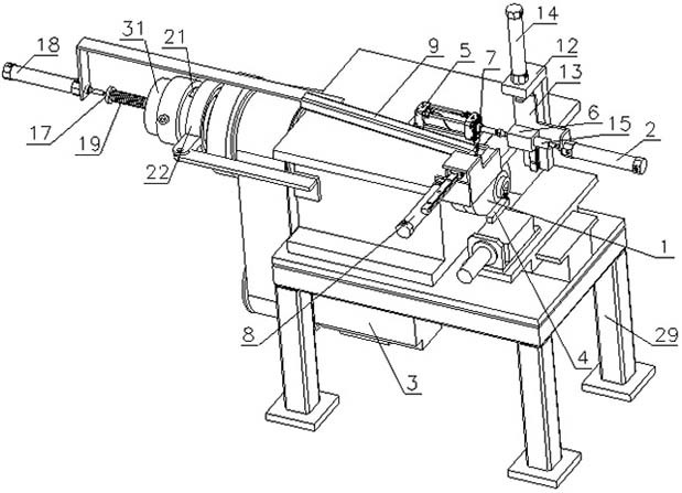
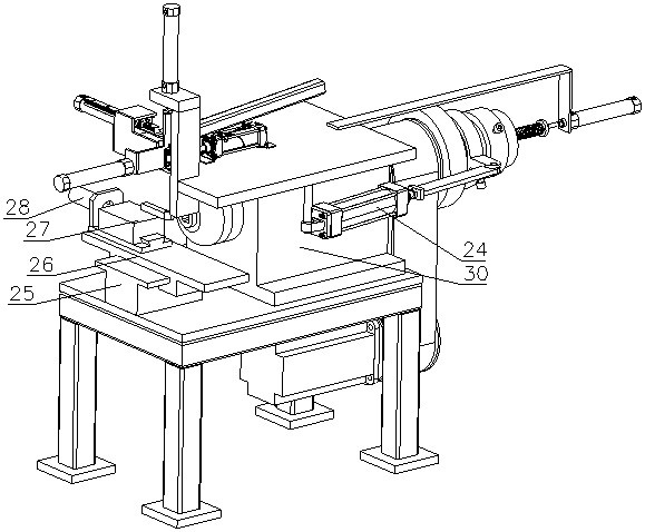
[0048] like figure 1 and figure 2 Shown, the present invention is a kind of oil bearing chamfering device, comprises frame 29. Frame 29 one end is equipped with rotating shaft seat 30, and rotating shaft seat 30 is installed with the rotating shaft 1 that realizes the rotating connection by bearing; Motor 3 is installed below frame 29 top plates, and motor 3 is a servo motor, and active synchronous belt pulley is installed on the driving shaft, and the driving and driven synchronous belt pulleys are linked by synchronous belt.
[0049] like Figure 7-9 As shown, the head of the rotating shaft 1 is provided with a square hole for clamping the oil-impregnated bearing, and the tail is sleeved with a rotating shaft sleeve 31, which is fixed by a plurality of evenly distributed tightening bolts. A cavity is provided between the end of the rotating shaft sleeve 31 and the tail of the rotating shaft 1 .
[0050] The present invention is also provided with a push assembly, includ...
Embodiment 2
[0058] Compared with Embodiment 1, the difference is: in order to vacate the lifting space for placing the tube 6, a distance is provided between the placing tube 6 and the rotating shaft 1, and when the first cylinder 2 pushes the oil-impregnated bearing into the rotating shaft 1, the oil-impregnated bearing easy to drop, so if Figure 13 and Figure 14 As shown, a driving rod 15 is installed on the piston rod of the first cylinder 2, and the end of the driving rod 15 is provided with a protrusion 16 for inserting into the inner hole of the oil-impregnated bearing.
Embodiment 3
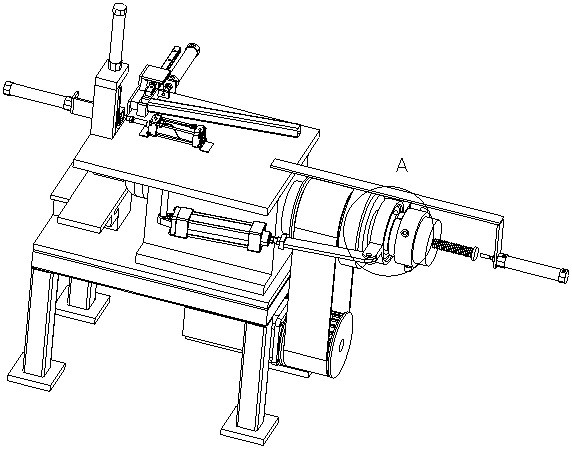
[0060] Compared with Embodiment 1, the difference is: as Figure 3-6 As shown, a first shaft portion and a second shaft portion are sequentially provided between the driven synchronous pulley and the rotating shaft sleeve 31, and the diameter of the second shaft portion is larger than that of the first shaft portion, as shown in Figure 10 and Figure 11 As shown, a T-shaped slot is provided near the second shaft part to the first shaft part, and a T-shaped pressing rod 21 is clamped in the T-shaped slot, and the connection between the pressing rod 21 and the T-shaped slot is realized by the second spring 20. Elastic connection. One end of the pressing rod 21 facing the first shaft part is provided with a guiding slope.
[0061] The pressing rod 21 is driven by a swing assembly. The oscillating assembly includes a ring base 22 sleeved on the first shaft portion, and a self-aligning bearing 23 sleeved on the rotating shaft 1 is installed in the ring base 22 . One end of the...
PUM
 Abstract
Description
Claims
Application Information
 - R&D
- Intellectual Property
- Life Sciences
- Materials
- Tech Scout
- Unparalleled Data Quality
- Higher Quality Content
- 60% Fewer Hallucinations
Browse by: Latest US Patents, China's latest patents, Technical Efficacy Thesaurus, Application Domain, Technology Topic, Popular Technical Reports.
© 2025 PatSnap. All rights reserved.Legal|Privacy policy|Modern Slavery Act Transparency Statement|Sitemap|About US| Contact US: help@patsnap.com


