Synchronous punching mechanism

A synchronous, punching device technology, applied in the direction of metal processing, etc., can solve the problems such as the paper dust discharge mechanism is not smooth, can not be completely cleaned, does not have multiple holes, etc.

Pending Publication Date: 2021-12-14
SUZHOU DEQI INTELLIGENT TECH CO LTD
View PDF0 Cites 0 Cited by
  • Summary
  • Abstract
  • Description
  • Claims
  • Application Information

AI Technical Summary

Problems solved by technology

[0003] Existing equipment only punches a single hole, and does not have the function of punching multiple holes at the same time, which takes too long. Moreover, the paper dust discharge mechanism of the current multi-hole equipment is not smooth, and it cannot be completely cleaned.

Method used


Image

  • Synchronous punching mechanism
  • Synchronous punching mechanism
  • Synchronous punching mechanism

Examples


Embodiment 1

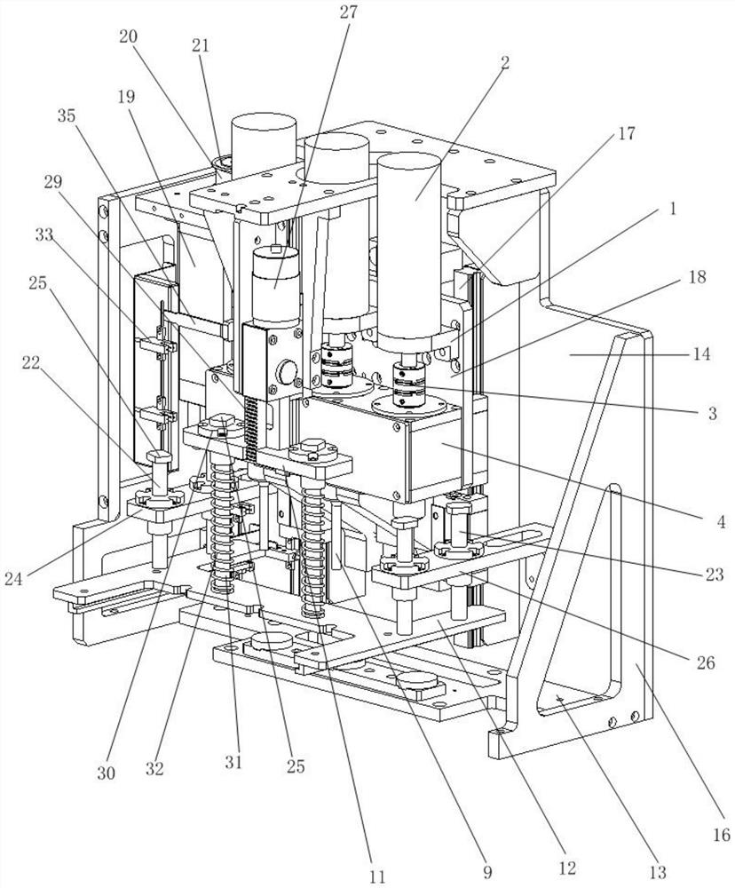
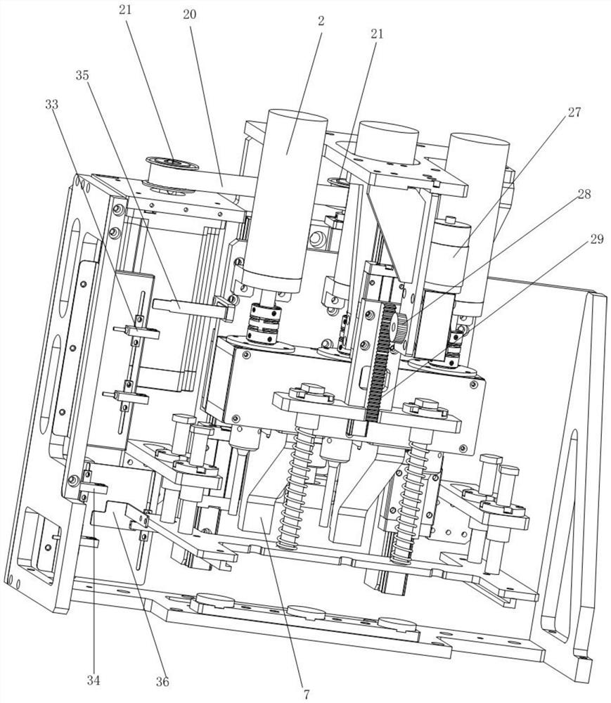
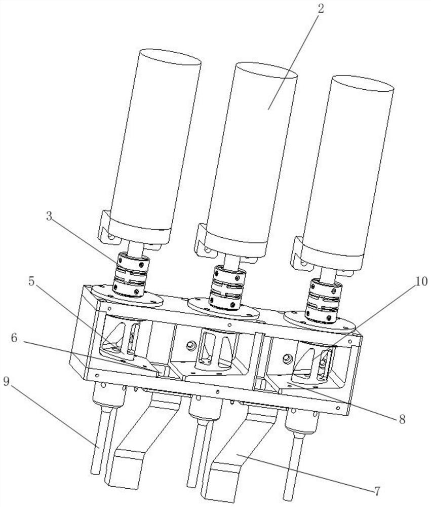
[0051] In this specific example Figure 1 to Figure 5The shown synchronous punching mechanism includes a frame, a paper pressing device installed in the frame, and a punching device installed on the backboard 18 in the frame. The punching device includes a vertical board 1 fixed on the backboard 18 And several DC motors 2 erected on the vertical plate 1, each DC motor 2 is connected with a hollow punching shaft 5 located in the paper scrap collection box 4 through a coupling 3, and the adjacent punched holes are located in the paper scrap collection box 4 The inner bottom surface between the shafts 5 is provided with a paper dust collection port 6, each paper dust collection port 6 is connected with a deflector 7, and the bottom bearing of each perforated shaft 5 is fixed on one side of the paper dust collection port 6 and The paper scraps are directed to the drainage block 8 of the paper scrap collection port 6, the bottom end of the punching shaft 5 is connected with a hollo...

Embodiment 2

[0055] In this specific example Figure 1 to Figure 5 The shown synchronous punching mechanism includes a frame, a paper pressing device installed in the frame, and a punching device installed on the backboard 18 in the frame. The punching device includes a vertical board 1 fixed on the backboard 18 And several DC motors 2 erected on the vertical plate 1, each DC motor 2 is connected with a hollow punching shaft 5 located in the paper scrap collection box 4 through a coupling 3, and the adjacent punched holes are located in the paper scrap collection box 4 The inner bottom surface between the shafts 5 is provided with a paper dust collection port 6, each paper dust collection port 6 is connected with a deflector 7, and the bottom bearing of each perforated shaft 5 is fixed on one side of the paper dust collection port 6 and The paper scraps are directed to the drainage block 8 of the paper scrap collection port 6, the bottom end of the punching shaft 5 is connected with a holl...

Embodiment 3

[0059] In this specific example Figure 1 to Figure 5 The shown synchronous punching mechanism includes a frame, a paper pressing device installed in the frame, and a punching device installed on the backboard 18 in the frame. The punching device includes a vertical board 1 fixed on the backboard 18 And several DC motors 2 erected on the vertical plate 1, each DC motor 2 is connected with a hollow punching shaft 5 located in the paper scrap collection box 4 through a coupling 3, and the adjacent punched holes are located in the paper scrap collection box 4 The inner bottom surface between the shafts 5 is provided with a paper dust collection port 6, each paper dust collection port 6 is connected with a deflector 7, and the bottom bearing of each perforated shaft 5 is fixed on one side of the paper dust collection port 6 and The paper scraps are directed to the drainage block 8 of the paper scrap collection port 6, the bottom end of the punching shaft 5 is connected with a holl...


PUM


Abstract

The invention relates to a synchronous punching mechanism. The mechanism comprises a frame, a paper pressing device erected in the frame and a punching device erected on a back plate in the frame, and the punching device comprises a vertical plate fixed to the back plate and a plurality of direct current motors erected on the vertical plate. Each direct-current motor is connected with a hollow punching shaft located in a paper scrap collecting box through a coupler, paper scrap collecting openings are formed in the inner bottom face, between every two adjacent punching shafts, in the paper scrap collecting box, and each paper scrap collecting opening is connected with a flow guiding device. A bottom bearing of each punching shaft is fixed to a drainage block which is located at one side of the paper scrap collecting opening and guides paper scraps to the paper scrap collecting opening, the bottom end of each punching shaft is connected with a hollow drilling tool, and a plurality of connecting holes which are communicated with the drilling tools through inner cavities of the punching shafts are formed in the outer walls of the punching shafts. The paper pressing device comprises a lifting device and a transverse plate controlled by the lifting device to ascend and descend, and a paper pressing plate is elastically connected to the transverse plate. The invention provides the synchronous punching mechanism capable of realizing high-efficiency punching.

Description

technical field [0001] The invention relates to the field of mechanical production, in particular to a synchronous punching mechanism. Background technique [0002] With the development of society, rising labor costs, the rise of the automation industry, and the widespread use of automation equipment, it is irreplaceable. The vigorous promotion of automation equipment, an important tool, can save a lot of manpower and labor for various industries. physical resources. Improve product quality and increase output value. [0003] Existing equipment only punches a single hole, and does not have the function of punching multiple holes at the same time, which takes too long. In addition, the paper dust discharge mechanism of the current multi-hole equipment is not smooth, and it cannot be completely cleaned. [0004] In view of the above-mentioned defects, the designer actively researches and innovates in order to create a synchronous punching mechanism to make it more industrial...

Claims


Application Information

Patent Timeline
Patent Type & Authority Applications(China)
IPC IPC(8): B26F1/16B26D7/02B26D7/18
CPCB26F1/16B26D7/025B26D7/18
Inventor 洪健
Owner SUZHOU DEQI INTELLIGENT TECH CO LTD
Why Eureka
Try Eureka