
Steel bar conveying method

A technology of steel bars and conveying rollers, applied in the direction of conveyor objects, transportation and packaging, roller tables, etc., can solve problems such as low efficiency, achieve the effect of improving efficiency, reducing power requirements, and eliminating safety risks of manual hoisting

Active Publication Date: 2021-12-14
ANYANG HELI CHUANGKE METALLURGY NEW TECH RES & DEV
View PDF9 Cites 0 Cited by
  • Summary
  • Abstract
  • Description
  • Claims
  • Application Information

AI Technical Summary

Problems solved by technology

In some space constraints, especially in renovation projects, it is necessary to change a certain angle during the conveying process of steel bars to reach the designated area, because the finished steel bars are in the shape of long bundles, and the length is generally more than 10 meters, so the linear conveyor roller table It cannot solve the problem of steel bar turning. In the case of small angle changes, curved roller tables can be designed to realize conveying. However, in the case of angle changes, such as right-angle steering, it is impossible to realize the spatial arrangement through curved roller tables. This kind of large-angle steering is basically a right-angle steering in order to save space in production transformation and equipment layout. In this case, the conveyor roller table is generally separated according to a certain angle, and it is manually hoisted at the turning. After the steel bar completes the turn, it is placed on the subsequent roller table to continue conveying. This operation requires at least two professionals for hoisting, and there are safety risks and low efficiency.

Method used


Image

  • Steel bar conveying method
  • Steel bar conveying method
  • Steel bar conveying method

Examples


Embodiment Construction

[0020] In order to more fully explain the implementation of the present invention, the implementation examples of the present invention are provided, and these implementation examples are only illustrations of the present invention, and do not limit the scope of the present invention.

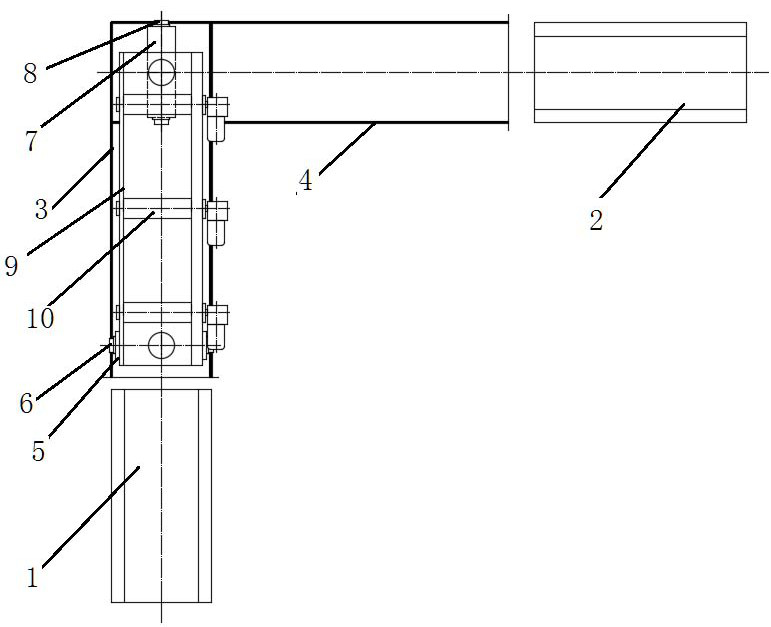
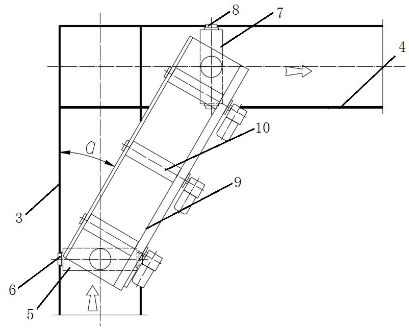
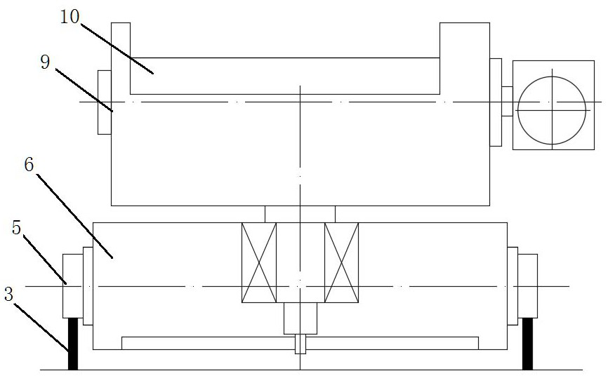
[0021] Each mark in the attached drawings is: 1: front conveyor roller table; 2: rear conveyor roller table; 3: track A; 4: track B; 5: drive box 1; 6: track wheel A; 7: drive box 2; 8: track wheel B; 9: turntable; 10: roller.

[0022] The definition of the front and rear directions in this application is: the direction of reinforcement delivery is the rear.

[0023] A steel bar conveying method, the conveying method is used for conveying bundled straight steel bars, the conveying method adopts a steel bar conveying device for conveying, and the described reinforcing bar conveying device includes a front section conveying roller table 1, a rear section Conveyor roller table 2, the front convey...


PUM


Abstract

A steel bar conveying method comprises the steps that S1, when a steel bar bundle reaches the tail end of a front-section conveying roller way, a rotating roller on a rotating table is started; S2, when the rear end of a steel bar reaches a stop position on the rotating table, a driving motor of a rotating roller is stopped, and a first driving box, a rail wheel A in a second driving box and a driving motor of a rail wheel B are started while the driving motor of the rotating roller is stopped; S3, the rotating table is driven by the first driving box and the second driving box to run along respective rails, the first driving box runs at a fixed speed V1, and the movement speed V2 of the second driving box is a function of the angle a; S4, when the rotating table and a rear-section conveying roller way are in the same direction, the first driving box and the second driving box stop; S5, the rotating roller is started, and the steel bar is conveyed to the rear-section conveying roller way from the rotating table; and S6, the rotating table is reset. By means of the steel bar conveying method, steel bar steering conveying can be achieved in a limited space.

Description

technical field [0001] The invention relates to post-transportation in steel bar production, in particular to a transport method in the scene where straight steel bars need to be turned after being cut and bundled, and belongs to the technical field of steel bar production. Background technique [0002] In the production of straight steel bars, the steel bars cut according to the fixed length are collected into bundles, and after being wrapped by a baler, they are generally transported to a designated area by a conveyor roller driven by a driving force, and then hoisted into the warehouse by a crane. In some space constraints, especially in renovation projects, it is necessary to change a certain angle during the conveying process of steel bars to reach the designated area, because the finished steel bars are in the shape of long bundles, and the length is generally more than 10 meters, so the linear conveyor roller table It cannot solve the problem of steel bar turning. In ...

Claims


Application Information

Patent Timeline
IPC IPC(8): B65G13/06B65G47/52
CPCB65G13/06B65G47/52
Inventor 夏维玺丁晓冰李伟张明杰
Owner ANYANG HELI CHUANGKE METALLURGY NEW TECH RES & DEV
Learn More