Thin plate carrying device for industrial production
A technology for handling devices and sheets, which is applied in the directions of transportation and packaging, conveyors, conveyor objects, etc., can solve the problems of a large number of manual labor, reduced performance, and inability to use sheets, so as to improve work efficiency and performance, and is not easy to bend. or deformation, the effect of reducing the amount of manual handling
- Summary
- Abstract
- Description
- Claims
- Application Information
AI Technical Summary
Problems solved by technology
Method used
Image
Examples
Embodiment example 1
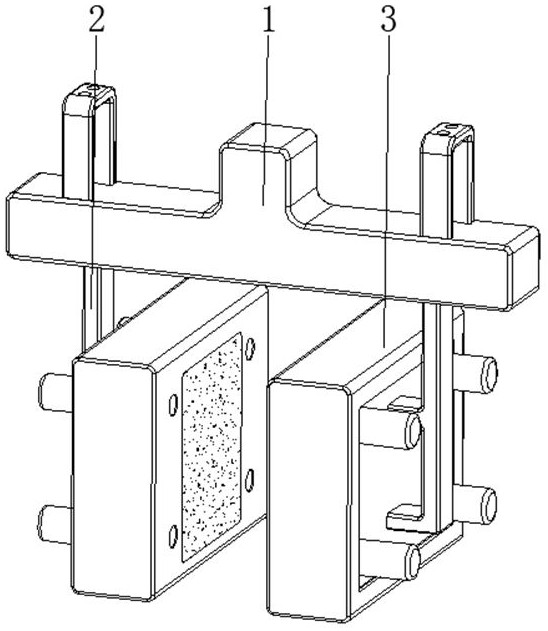
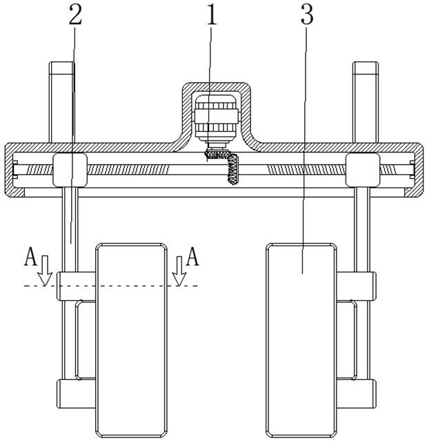
[0034] see Figure 1-7 , the present invention provides a technical solution: a thin plate handling device for industrial production, including a driving mechanism 1, a connecting frame 2, and a clamping device 3, the connecting frame 2 is arranged at the top center of the driving mechanism 1, and the clamping device 3 is arranged at the bottom of the surface of the connecting frame 2;
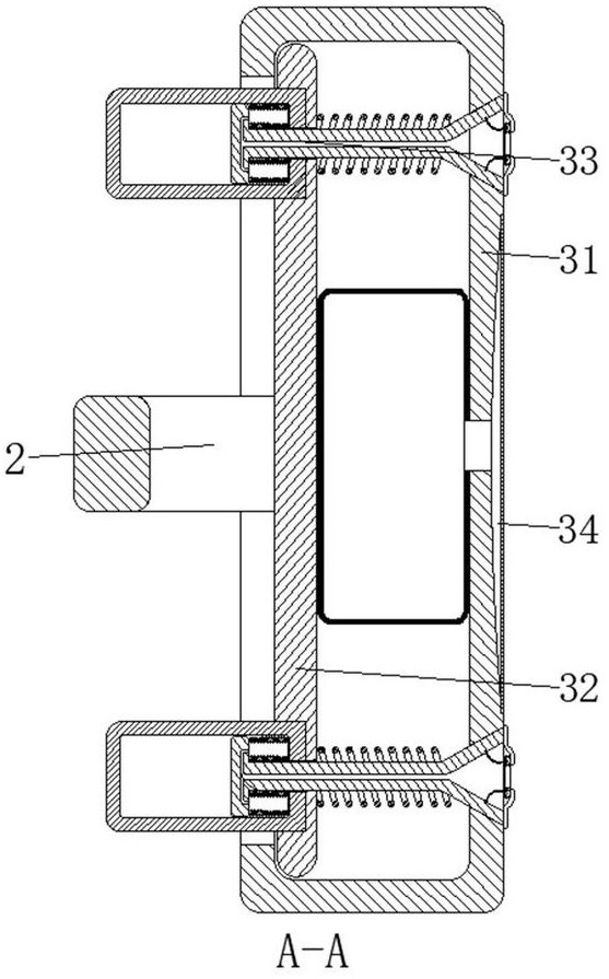
[0035] The clamping device 3 is provided with a housing 31, a sliding plate 32, an adsorption device 33, and a pressing and expanding device 34. The housing 31 is located directly below the driving mechanism 1, and the sliding plate 32 is slidably connected to the inside of the housing 31 and is close to the surface side to absorb The device 33 is arranged between the two sides corresponding to the inner wall of the housing 31 and the surface of the slide plate 32, and the pressing and expanding device 34 is arranged inside the housing 31, and the driving mechanism 1 is used as the driving for...
Embodiment example 2
[0037] The adsorption device 33 is provided with a support member 331, a sealing device 332, a piston cylinder 333, a return spring 334, and a stretching air bag 335. One end of the support member 331 is fixedly connected to the inner wall of the housing 31, and the sealing device 332 is arranged on the end of the support member 331. part and close to the surface of the housing 31, the piston barrel 333 is slidably connected to the end of the support 331 away from the sealing device 332, and the return spring 334 is fixed between the end of the support 331 and the two sides corresponding to the surface of the slide plate 32, stretching The air bag 335 is disposed between the end of the support member 331 and the two sides corresponding to the inner wall of the piston cylinder 333 .
[0038] An air channel 3301 is provided in the center of the support member 331, and the air channel 3301 communicates with the stretching air bag 335. One end of the piston cylinder 333 is fixedly ...
Embodiment example 3
[0043] Drive mechanism 1 is provided with support frame 11, transmission screw mandrel 12, slide block 13, and drive screw mandrel 12 is rotatably connected between the two sides corresponding to the inner wall of support frame 11, and slide block 13 is slidably connected in the inside of support frame 11, slides The block 13 is threadedly connected with the transmission screw mandrel 12, and the bottom of the slide block 13 is fixedly connected with the top of the connecting frame 2.
[0044] A motor 101 is fixedly connected to the central position of the inner wall top of the support frame 11, and the output shaft of the motor 101 is connected to the surface of the transmission screw 12 through a conical gear set 102. .
[0045] The end of the transmission screw 12 is connected to the inner wall of the support frame 11 through bearing rotation, and the corresponding position on the surface of the transmission screw 12 is in the opposite thread direction. The motor 101 is use...
PUM
 Abstract
Description
Claims
Application Information
 - R&D
- Intellectual Property
- Life Sciences
- Materials
- Tech Scout
- Unparalleled Data Quality
- Higher Quality Content
- 60% Fewer Hallucinations
Browse by: Latest US Patents, China's latest patents, Technical Efficacy Thesaurus, Application Domain, Technology Topic, Popular Technical Reports.
© 2025 PatSnap. All rights reserved.Legal|Privacy policy|Modern Slavery Act Transparency Statement|Sitemap|About US| Contact US: help@patsnap.com


