
Mold for battery aluminum shell production

A battery aluminum shell and mold technology, applied in battery pack components, circuits, molding tools, etc., can solve problems such as alignment, efficiency, yield impact, impact on productivity and efficiency, and impact on production operations, and achieve improved cooling. range and duration, increase productivity, reduce the effect of trimming operations

Inactive Publication Date: 2021-12-17
李冰
View PDF0 Cites 0 Cited by
  • Summary
  • Abstract
  • Description
  • Claims
  • Application Information

AI Technical Summary

Problems solved by technology

[0003] From the perspective of large-scale application in the market, although the length of the battery cell can effectively reduce the application of structural components, it is undeniable that at the same level of technology, the longer the battery cell, the lower its alignment, efficiency, and yield in the production process. will be affected
Therefore, in order to realize the manufacture of L6 batteries, it is necessary to work hard on the process and manufacturing. As long as the safety issues can be systematically solved, and related issues such as material gas production can be well controlled, this can greatly enrich the multi-scenario application of the vehicle. The lower mileage selection allows OEMs to have more room for choice. The existing molds for battery aluminum case production are prone to damage under high-intensity production operations, affecting normal production operations, thereby affecting production capacity and efficiency. When feeding, the debris is easy to stay in the placement frame, resulting in an increase in the failure rate, thereby increasing the production cost

Method used


Image

  • Mold for battery aluminum shell production
  • Mold for battery aluminum shell production
  • Mold for battery aluminum shell production

Examples


Embodiment Construction

[0028] The following will clearly and completely describe the technical solutions in the embodiments of the present invention with reference to the accompanying drawings in the embodiments of the present invention. Obviously, the described embodiments are only some, not all, embodiments of the present invention. Based on the embodiments of the present invention, all other embodiments obtained by persons of ordinary skill in the art without making creative efforts belong to the protection scope of the present invention.

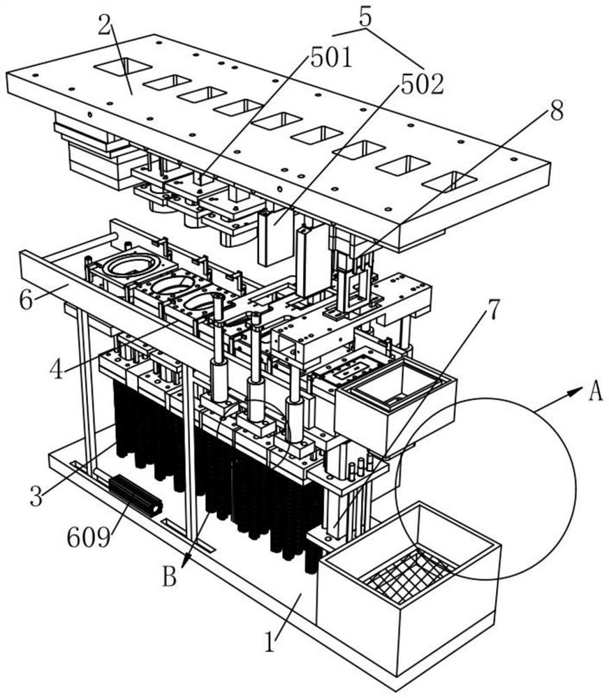
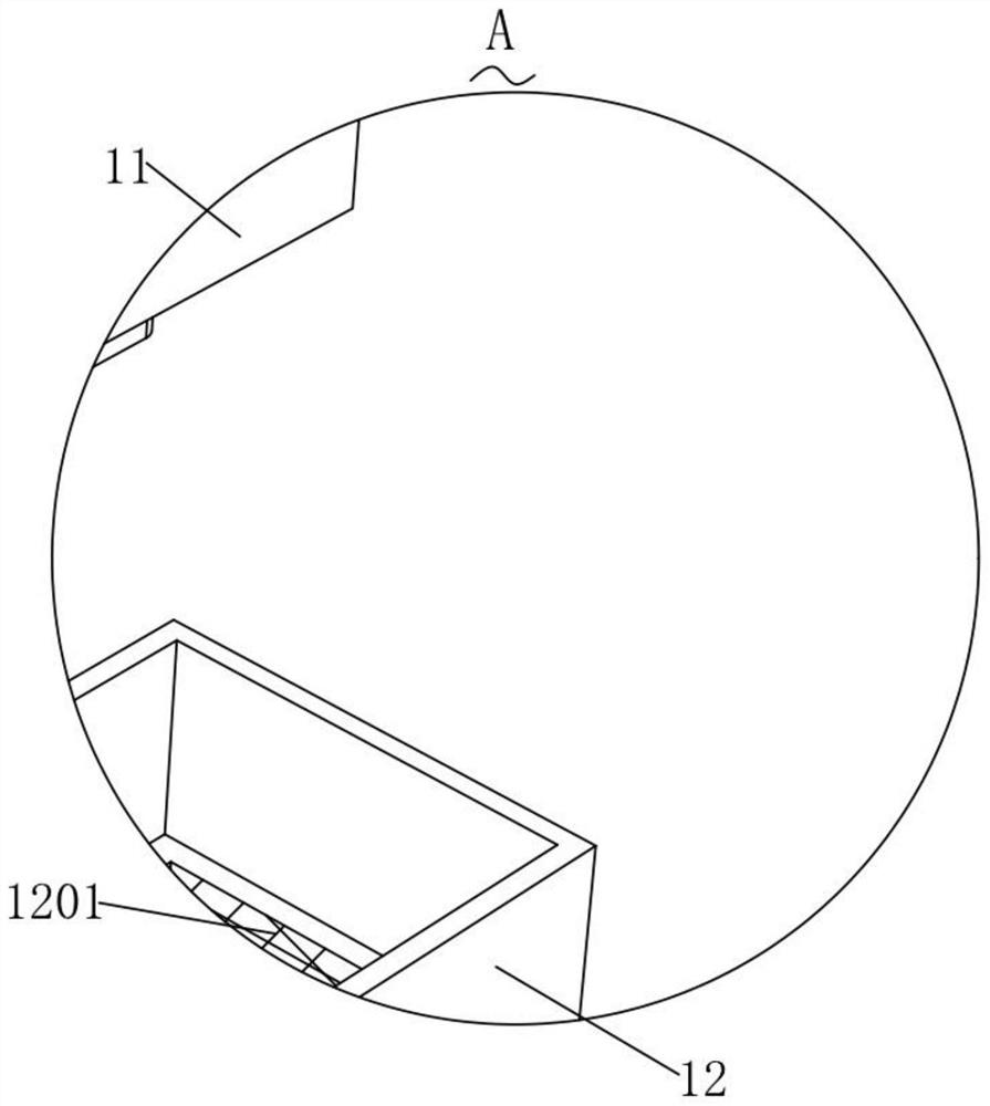
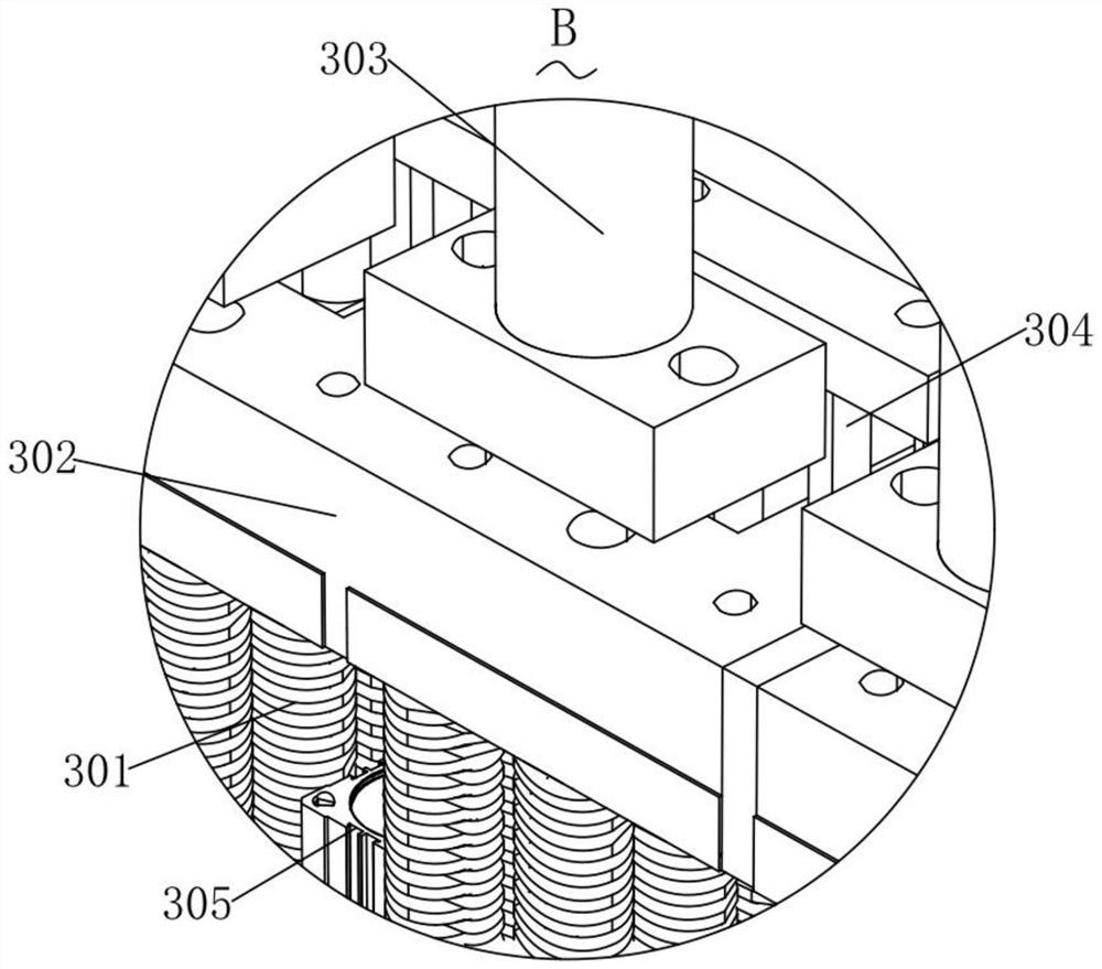
[0029] During specific implementation: if Figure 1-9As shown, a mold for the production of battery aluminum shells includes a bottom plate 1 and a mounting plate 2, the top of the bottom plate 1 is provided with a uniformly distributed shock-absorbing support structure 3, and the top of the shock-absorbing support structure 3 is provided with a lower mold structure 4 , the bottom end of the mounting plate 2 is provided with an evenly distributed upper mold st...


PUM


Abstract

The invention relates to the technical field of battery aluminum shell processing equipment, in particular to a mold for battery aluminum shell production. The mold comprises a bottom plate and a mounting plate, the top end of the bottom plate is provided with uniformly distributed damping support structures, and the top ends of the damping support structures are provided with lower mold structures; and upper mold structures which are uniformly distributed are arranged at the bottom end of the mounting plate. The service life of the mold is prolonged, meanwhile, the maintenance time is shortened, and therefore the production efficiency and the production cost are improved; and meanwhile, condensate can cool battery aluminum shells machined through the mold, a spiral condenser pipe increases the contact area between the condenser pipe and the battery aluminum shells machined through the mold, and meanwhile, the circulation time of the condensate in the condenser pipe is prolonged, so that the range and the duration of cooling the battery aluminum shells by the condensate are expanded, the cooling efficiency is improved, the battery aluminum shells can be rapidly cooled and solidified, the production efficiency and the product quality of the battery aluminum shells are improved, and the production cost is saved while the quality is improved.

Description

technical field [0001] The invention relates to the technical field of battery aluminum case processing equipment, in particular to a mold used for the production of battery aluminum case. Background technique [0002] With the development and changes of domestic and foreign situations, in order to better adapt to the development needs of my country's new energy vehicle industry, further relax the entry threshold, stimulate market vitality, strengthen interim and post-event supervision, and promote the high-quality development of my country's new energy vehicle industry. Power battery industry Since its development, it has been pursuing the use of lightest materials in a limited space to allow mobile vehicles to obtain greater energy. Among them, an important direction is: make full use of the space as much as possible, and reduce the auxiliary parts that do not generate energy while ensuring safety, which is called structural innovation in the industry. At the same time, in...

Claims


Application Information

Patent Timeline
IPC IPC(8): B21D37/10B21D22/02B21D37/16F16F15/067B21D45/00B21D43/28H01M50/119
CPCB21D37/10B21D22/02B21D37/16F16F15/067B21D45/00B21D43/28H01M50/119Y02E60/10
Inventor 李冰杨轶李二甫
Owner 李冰
Learn More