Cast-in-place pile and construction method thereof

A technology of cast-in-situ piles and pile bodies, which is applied in sheet pile walls, foundation structure engineering, construction, etc., can solve problems such as low strength and poor fit, and achieve the effect of improving strength and increasing strength

Pending Publication Date: 2021-12-17
德清县亿胜建设有限公司
View PDF7 Cites 0 Cited by
  • Summary
  • Abstract
  • Description
  • Claims
  • Application Information

AI Technical Summary

Problems solved by technology

[0004] In view of the above-mentioned related technologies, the inventor believes that the existing cast-in-place piles are only placed in the pile grooves and have poor cooperation with the ground, and the strength of fixing them on the ground is not high

Method used


Image

  • Cast-in-place pile and construction method thereof
  • Cast-in-place pile and construction method thereof
  • Cast-in-place pile and construction method thereof

Examples


Embodiment Construction

[0044] The following is attached Figure 1-5 The application is described in further detail.

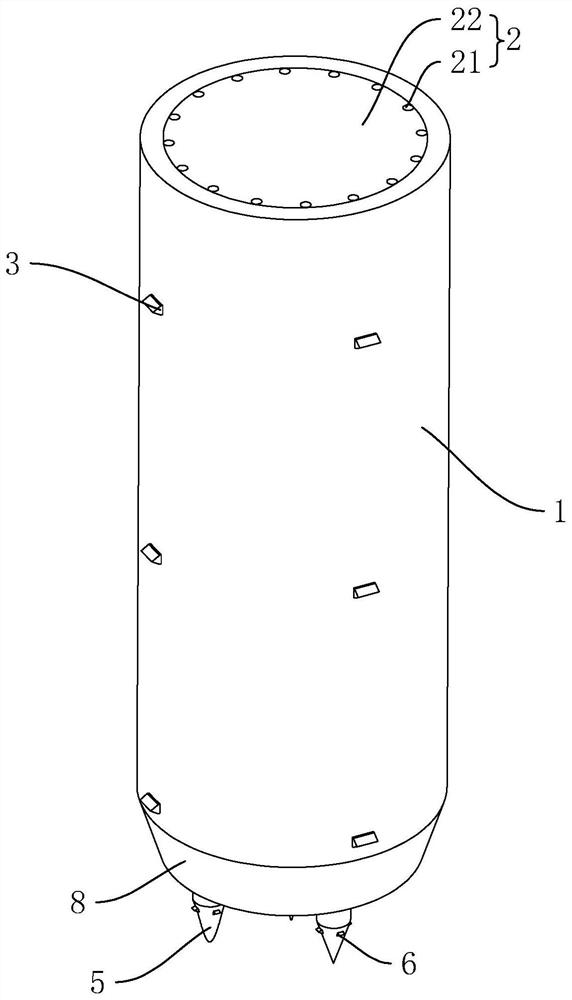
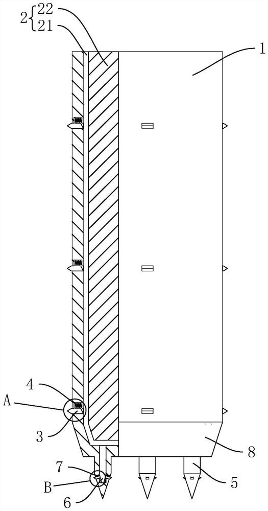
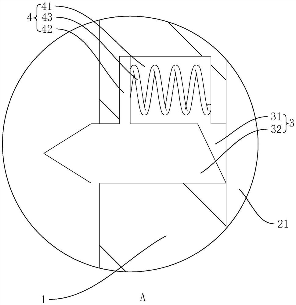
[0045] The embodiment of the present application discloses a cast-in-situ pile, which includes a pile body 1 and a concrete column 2 poured in the pile body 1. The pile body 1 is a cylindrical column body, and a pouring groove is provided in the pile body 1, and the pouring groove is along the length of the pile body 1. The direction extends and runs through one end of the pile body 1 in the length direction. The concrete column 2 is poured from the end of the pouring groove through the pouring groove into the pouring groove. The length direction is divided into three pairs, and each pair has four groups evenly arranged in the circumferential direction of the pile body 1. The reinforcement component 3 includes a reinforcement groove 31 set on the pile body 1 perpendicular to the pile body 1 and a reinforcement groove 31 slidingly arranged in the reinforcement groove 31. Block 32, th...


PUM


Abstract

The invention relates to a cast-in-place pile. The cast-in-place pile comprises a pile body and a concrete column poured in the pile body, a plurality of sets of reinforcing assemblies are arranged in the circumferential direction of the pile body, and the reinforcing assemblies are arranged in the length direction of the pile body; each reinforcing assembly comprises a reinforcing groove and a reinforcing block, the reinforcing grooves are formed in the pile body in the mode of being perpendicular to the pile body, and the reinforcing blocks are slidably arranged in the reinforcing grooves; and one ends of the reinforcing blocks abut against the outer side wall of a concrete column, the other ends of the reinforcing blocks stretch out of the pile body, and the reinforcing blocks slide in the direction close to or away from the concrete column. The cast-in-place pile has the effect of improving the connection strength of the cast-in-place pile fixed to the ground.

Description

technical field [0001] The application relates to the field of building construction, in particular to a cast-in-place pile and a construction method thereof. Background technique [0002] Pile foundation is a commonly used foundation form in the field of civil engineering, and its use has a history of thousands of years. Cast-in-place pile is a pile structure made of reinforced concrete. Compared with ordinary hammer pile, cast-in-place pile has low noise and wide application range. [0003] For the existing cast-in-situ piles, the reinforcement cage is placed in the pre-dug pile groove, and then concrete is poured in the pile groove, and after the concrete is solidified, the house is built on the pile body. [0004] In view of the related technologies mentioned above, the inventor believes that the existing cast-in-situ piles are only placed in the pile grooves and have poor cooperation with the ground, and the strength of fixing them on the ground is not high. Contents...

Claims


Application Information

Patent Timeline
Patent Type & Authority Applications(China)
IPC IPC(8): E02D5/50
CPCE02D5/50
Inventor 白菲菲张孙胜杨淑芬
Owner 德清县亿胜建设有限公司
Why Eureka
Try Eureka