
Multi-stage sealing refrigeration valve

A valve and valve body technology, applied in the field of multi-stage sealed refrigeration valves, can solve the problems of valve core sealing, serious refrigeration valve service life, electromagnetic coil burning and other problems, and achieve the effect of ensuring tightness

Pending Publication Date: 2021-12-17
曾俊
View PDF0 Cites 0 Cited by
  • Summary
  • Abstract
  • Description
  • Claims
  • Application Information

AI Technical Summary

Problems solved by technology

[0003] However, the existing refrigeration valves still have the following deficiencies in the actual use process: first, because the traditional refrigeration valve controls the up and down movement of the iron core through the on-off point, and drives the valve core to move up and down above the valve seat to control the movement of the refrigeration valve. This makes it necessary to maintain sufficient pre-tightening force when the spool is in contact with the spool base in order to ensure the tightness between the spool and the spool base. This results in greater friction between the spool and the spool base when the spool is opened and closed. Therefore, the spool and spool base are prone to severe wear during repeated use, not only serious The service life of the refrigeration valve, and it is very easy to cause the sealing problem of the valve core after repeated use, resulting in leakage; secondly, when the electromagnetic coil is energized, a large amount of heat will be generated on the coil, which will easily cause the burning of the electromagnetic coil and affect the electromagnetic coil. coil life

Method used


Image

  • Multi-stage sealing refrigeration valve
  • Multi-stage sealing refrigeration valve
  • Multi-stage sealing refrigeration valve

Examples


Embodiment Construction

[0018] The following will clearly and completely describe the technical solutions in the embodiments of the present invention with reference to the accompanying drawings in the embodiments of the present invention. Obviously, the described embodiments are only some, not all, embodiments of the present invention. Based on the embodiments of the present invention, all other embodiments obtained by persons of ordinary skill in the art without making creative efforts belong to the protection scope of the present invention.

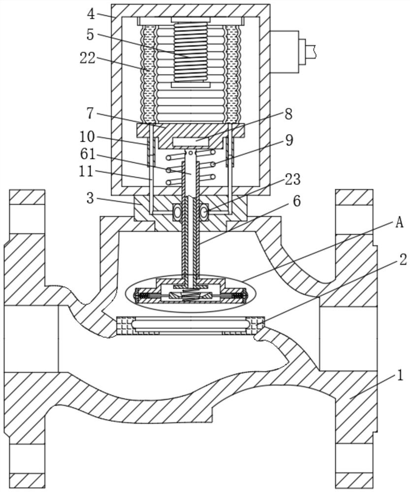
[0019] see figure 1 , a multi-stage sealed refrigeration valve, comprising a valve body 1, a valve core base 2 is fixedly installed inside the valve body 1, a sealing base 3 is fixedly connected to the upper end of the valve body 1, and an installation chamber 4 is fixedly connected to the upper end of the sealing base 3 , the upper part of the inner cavity of the installation chamber 4 is fixedly installed with an electromagnet 5, and the middle part of the b...


PUM


Abstract

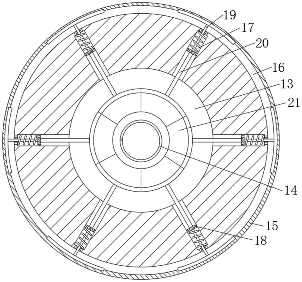
The invention relates to the technical field of refrigeration valves, and discloses a multi-stage sealing refrigeration valve. The multi-stage sealing refrigeration valve comprises a valve body, a valve element base is fixedly installed inside the valve body, and a sealing base is fixedly connected to the upper end of the valve body. Through arrangement of a hollow pipe, a valve element shell and a rubber ring, when the refrigeration valve is not powered on, the valve element shell moves downwards, the rubber ring cannot make close contact with the valve element base in the process, severe friction between the rubber ring and the valve element base when the rubber ring is closed is avoided, the service life of the valve element and the valve element base is prolonged, when the valve element shell moves downwards to coincide with the valve element base, the hollow pipe continues to move downwards, a circular plate presses a wedge-shaped block downwards, the supporting plate can expand towards the outer side till the rubber ring tightly abuts against the inner side wall of the valve element base, meanwhile, air inside the hollow circular pipe can enter an annular cavity, the rubber ring can be expanded, the side face of the rubber ring can be completely attached to the inner side wall of the valve element base everywhere, and the sealing performance of the valve element is guaranteed.

Description

technical field [0001] The invention relates to the technical field of refrigeration valves, in particular to a multi-stage sealed refrigeration valve. Background technique [0002] The refrigeration valve is a small flow, hard-sealed, normally closed solenoid valve. The refrigeration valve can be used for defrosting, flow direction control and on-off control of the refrigeration system. The basic structure of the refrigeration valve consists of a coil and a movable valve located in the coil. Composition of moving iron core. When the coil in the refrigeration valve is energized, a magnetic field will be generated to drive the iron core, and the valve will be opened through the movement of the iron core. The reset action of the valve is accomplished by the gravity of the valve core and the elastic force of the spring installed on its top. [0003] However, the existing refrigeration valves still have the following deficiencies in the actual use process: first, because the tr...

Claims


Application Information

Patent Timeline
IPC IPC(8): F16K1/00F16K1/36F16K31/06F16K41/10F16K41/04F16K49/00
CPCF16K1/00F16K1/36F16K31/0675F16K31/0655F16K41/10F16K41/04F16K49/005
Inventor 曾俊
Owner 曾俊
Learn More