Distributed magnetic ring structure

A distributed, magnetic ring technology, applied in the direction of measuring device magnets, measuring devices, instruments, etc., can solve the problems of unsatisfactory filtering effect, poor overcurrent capability, inconvenient maintenance, etc., to achieve management reliability and cost, improve Utilization and reliability improvement

Pending Publication Date: 2021-12-17
GUANGDONG GUANGDA ELECTRICAL
View PDF0 Cites 0 Cited by
  • Summary
  • Abstract
  • Description
  • Claims
  • Application Information

AI Technical Summary

Problems solved by technology

[0003] Later, the reactor was used for filtering, but in the process of use, it needs to be installed in a centralized manner, and the filtering effect is not ideal, the overcurrent capability is poor, and the maintenance is inconvenient and many other problems.

Method used


Image

  • Distributed magnetic ring structure
  • Distributed magnetic ring structure
  • Distributed magnetic ring structure

Examples


Embodiment Construction

[0026] Embodiments of the present invention are described in detail below, examples of which are shown in the drawings, wherein the same or similar reference numerals designate the same or similar elements or elements having the same or similar functions throughout. The embodiments described below by referring to the figures are exemplary only for explaining the present invention and should not be construed as limiting the present invention.

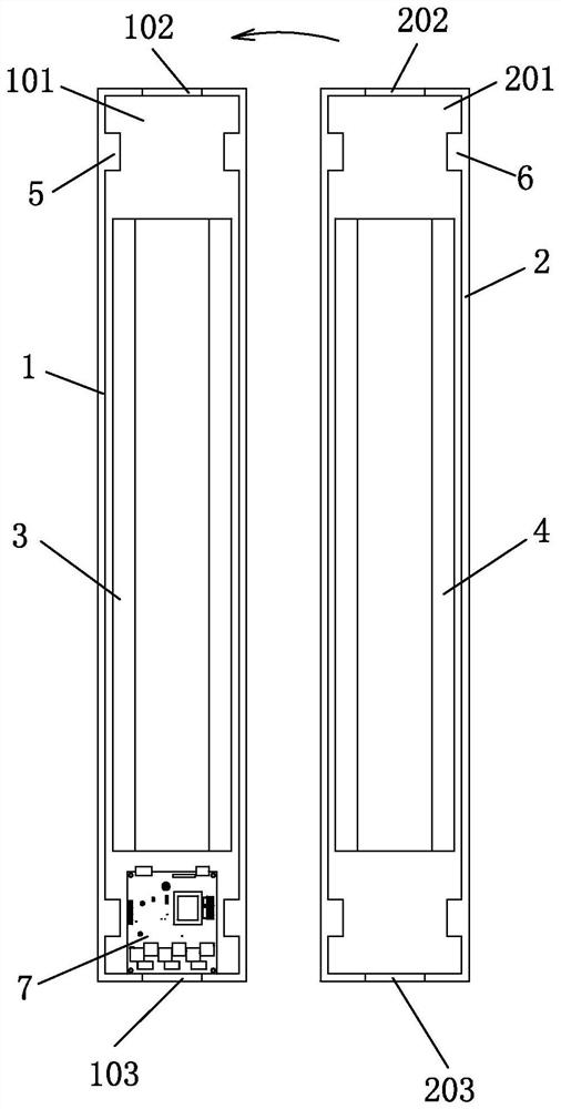
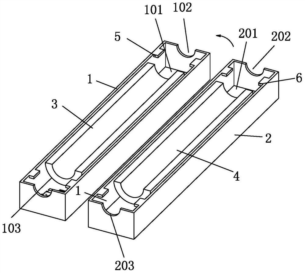
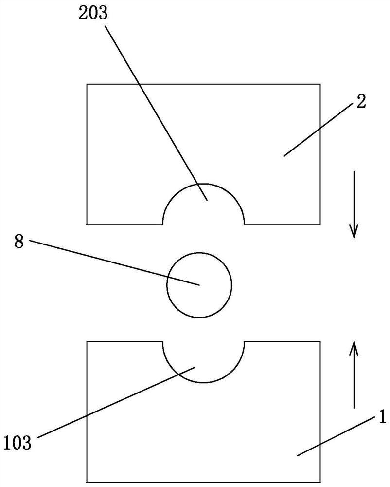
[0027] like Figure 1 to Figure 5 As shown, a distributed magnetic ring structure described in the present invention includes a first magnetic ring body 1, a second magnetic ring body 2 and a cable 8, and the first magnetic ring body 1 and the second magnetic ring body 2 are connected to each other. , the cable 8 passes between the first magnetic ring body 1 and the second magnetic ring body 2, an inner magnetic ring sleeve is provided between the first magnetic ring body 1 and the second magnetic ring body 2, and the inner magnetic ring...


PUM


Abstract

The invention particularly relates to a distributed magnetic ring structure, which comprises a first magnetic ring body, a second magnetic ring body and a cable, wherein the first magnetic ring body and the second magnetic ring body are connected with each other, the cable penetrates through the first magnetic ring body and the second magnetic ring body, an inner magnetic ring sleeve is arranged between the first magnetic ring body and the second magnetic ring body, is located on the cable side, and is electrically connected with a communication board, the communication board comprises a detection module, a data storage module and an RS485 communication module, the detection module, the data storage module and the RS485 communication module are sequentially connected, the inner magnetic ring sleeve is electrically connected to the detection module, and the data storage module is used for recording state parameters output by the detection module and allowing the communication module to read the state parameters. According to the invention, the first magnetic ring body, the second magnetic ring body and the inner magnetic ring sleeve are combined and installed on the cable in a distributed manner, so that the reliability can be improved, and the utilization rate of the existing power transmission infrastructure is improved; and the communication board plays a role in providing real-time line information;.

Description

technical field [0001] The invention relates to the technical field of cable equipment, in particular to a distributed magnetic ring structure. Background technique [0002] Cables generally filter out electromagnetic radiation by sheathing magnetic rings. As the service life of the cable increases, the impedance of the cable increases, and the electromagnetic radiation generated by the cable increases accordingly. [0003] Later, a reactor was used for filtering, but in the process of use, it needs to be installed in a centralized manner and has many problems such as unsatisfactory filtering effect, poor overcurrent capability, and inconvenient maintenance. Contents of the invention [0004] The purpose of the present invention is to overcome the above-mentioned technical problems and propose a distributed magnetic ring structure that provides real-time line information and is convenient for daily maintenance. [0005] A distributed magnetic ring structure described in ...

Claims


Application Information

Patent Timeline
Patent Type & Authority Applications(China)
IPC IPC(8): G01R1/16G01R31/08G01D21/02
CPCG01R1/16G01R31/085G01D21/02
Inventor 欧阳乾赞冯亚明黄文进吴文志
Owner GUANGDONG GUANGDA ELECTRICAL
Why Eureka
Try Eureka